Silicon single crystal producing method

a silicon single and production method technology, applied in the direction of crystal growth process, polycrystalline material growth, protective fluid, etc., can solve the problems of reducing the yield of silicon single, dislocation loop, stacking fault, precipitation,

Active Publication Date: 2018-02-27
SUMCO CORP
View PDF9 Cites 1 Cited by
  • Summary
  • Abstract
  • Description
  • Claims
  • Application Information

AI Technical Summary

Benefits of technology

[0021]According to the silicon single crystal producing method according to the present invention, it is possible to appropriately control an oxygen concentration in a pulled silicon single crystal to ensure homogeneity of the oxygen concentration of the single crystal in a growth axis direction. In addition, the method is sufficiently applicable to producing a silicon single crystal from which a large-diameter silicon wafer having a diameter of 300 mm or more can be cut.

Problems solved by technology

Such oxygen causes a precipitate, a dislocation loop, and a stacking fault, in a heat treatment process to produce a device using a wafer cut from the silicon single crystal.
A problem about the oxygen concentration in the silicon single crystal is in particular variations in oxygen concentration in a single crystal in a growth axis direction.
For this reason, the homogeneity of the oxygen concentration in a single crystal in a growth axis direction cannot be secured, resulting in a decreased yield in producing a silicon single crystal that has a narrow required range of oxygen concentration specifications between an upper limit value and a lower limit value.

Method used


Image

  • Silicon single crystal producing method
  • Silicon single crystal producing method
  • Silicon single crystal producing method

Examples


example 1

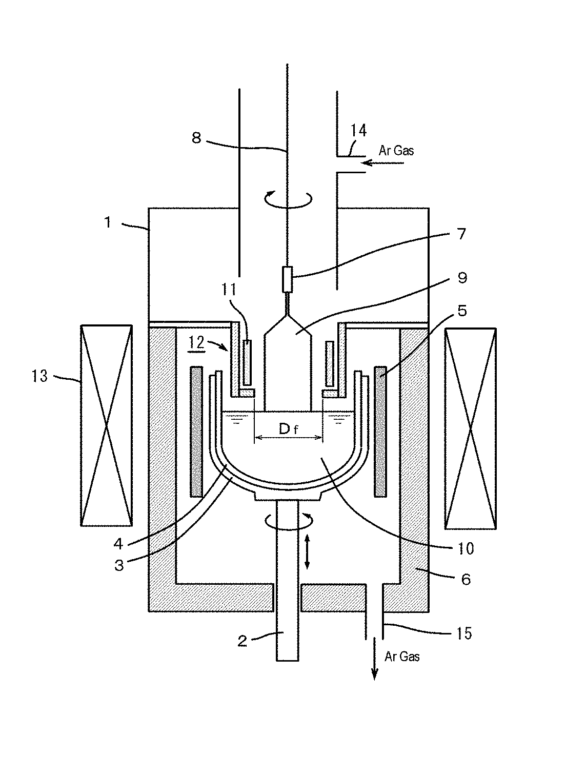
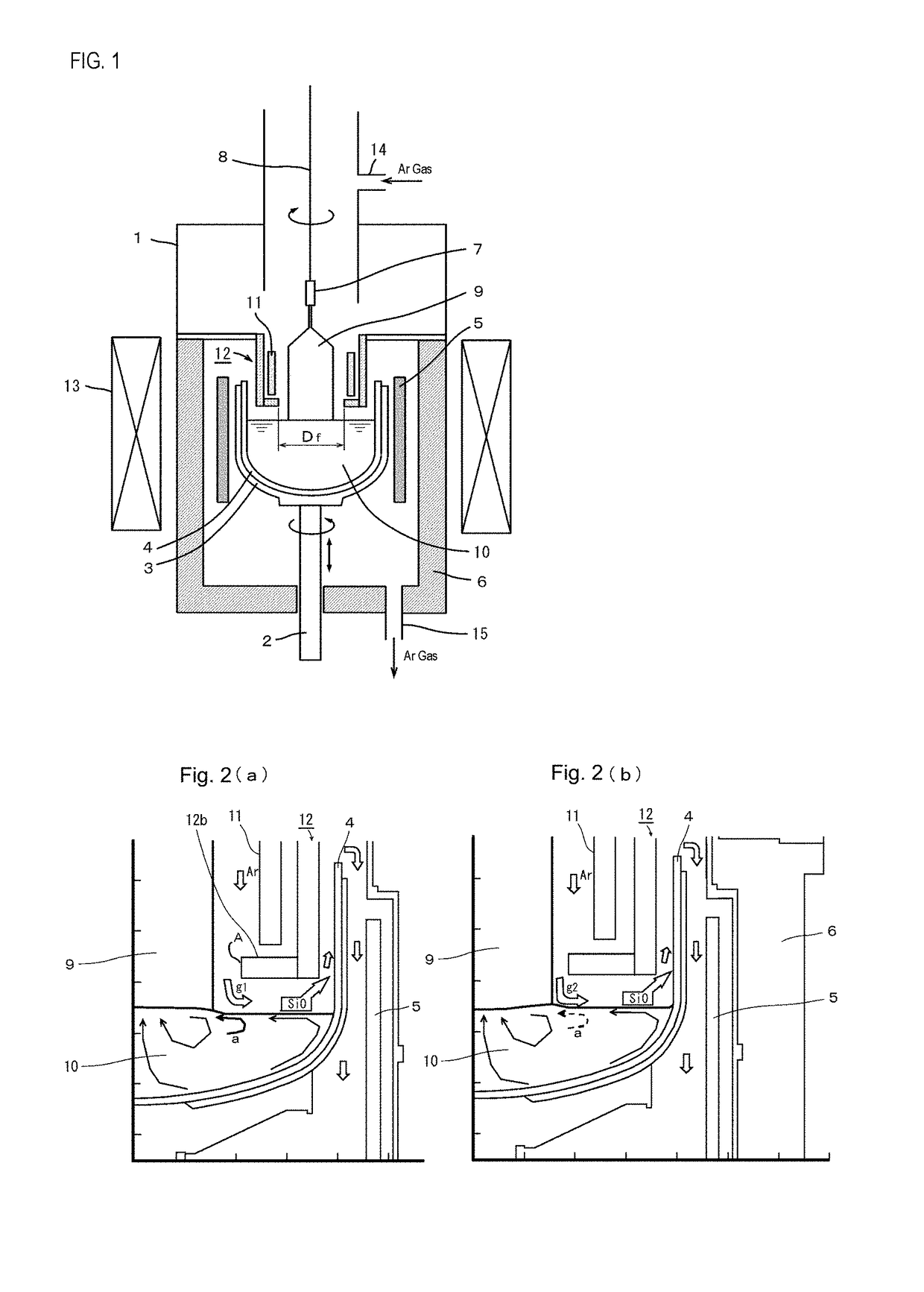
[0055]In consideration of the above-described result of study on the inert gas flow velocity through numerical simulations, for the cases where the gap-to-crystal-diameter ratio is low (0.37) and high (0.86), tests of pulling a silicon single crystal (having a crystal diameter of about 300 mm in both the cases) were conducted while changing an inert gas flow velocity at the gap portion between the exterior surface of a pulled single crystal and the lower-end opening edge of a heat shield (an Ar flow velocity in a crystal-heat shield space), and the concentration of oxygen incorporated into the single crystal was measured. Table 1 shows pulling test conditions together with the oxygen concentrations of the pulled single crystals.

[0056]The “Ar flow rate” is a flow rate of Ar gas introduced into the apparatus (volume velocity), which is measured as a volume of the Ar gas flowing per unit time at the standard temperature and pressure (0° C., 1 atmospheric pressure) in standard liters pe...

example 2

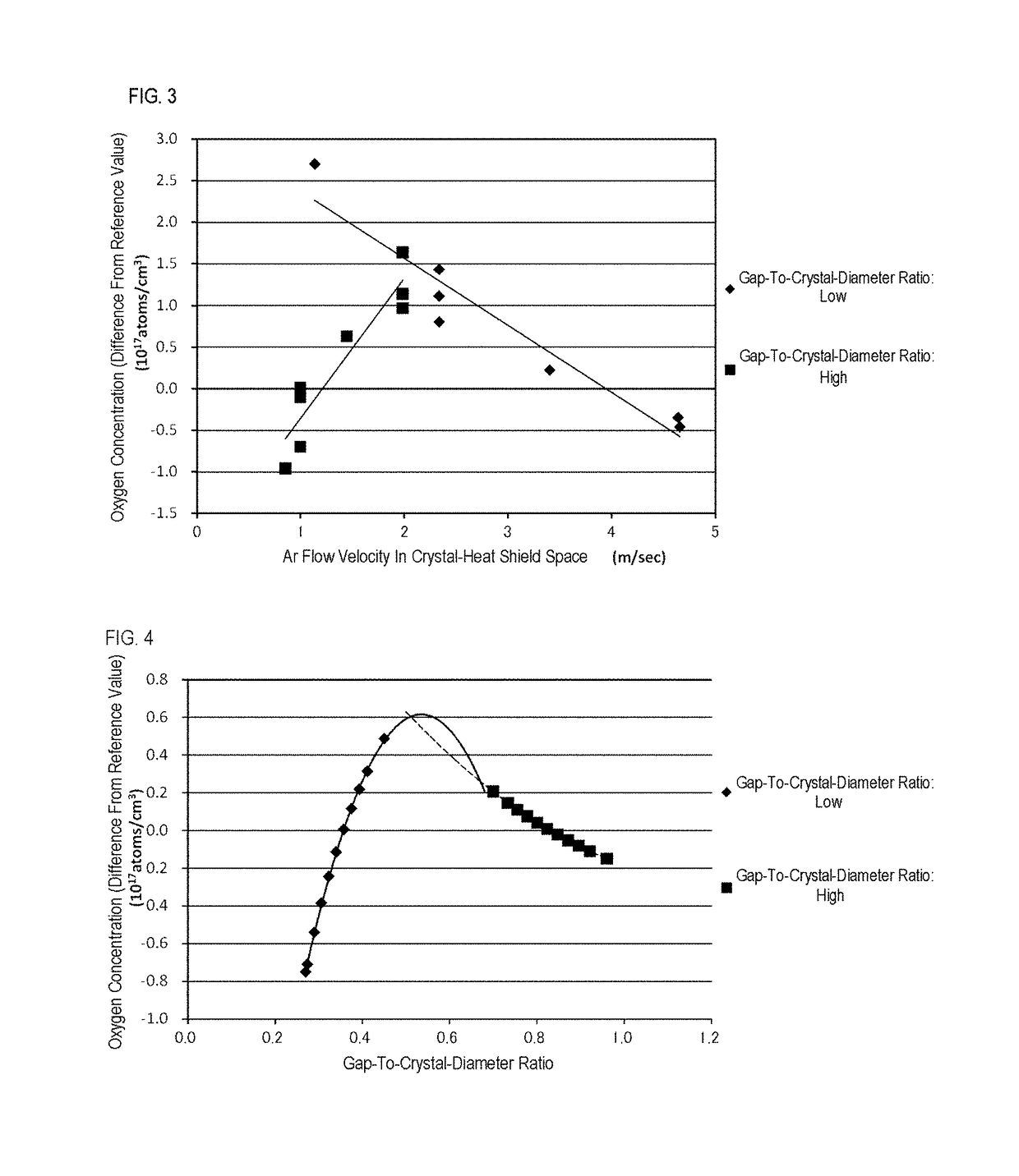
[0063]For each of the cases where the gap-to-crystal-diameter ratio of the heat shield is low and high, the relation between the gap-to-crystal-diameter ratio and the oxygen concentration in a pulled single crystal was investigated while changing the gap-to-crystal-diameter ratio by changing the diameter of the silicon single crystal. The flow rate of inert gas (Ar gas) introduced into the apparatus and the pressure in the apparatus were set constant.

[0064]The result is shown in FIG. 4. FIG. 4 is a diagram illustrating the relation between the gap-to-crystal-diameter ratio and the oxygen concentration in a pulled single crystal for the cases where the gap-to-crystal-diameter ratio of the heat shield is high and low.

[0065]As is clear from FIG. 4, in the case where the gap-to-crystal-diameter ratio of the heat shield is low (written in FIG. 4 as “GAP-TO-CRYSTAL-DIAMETER RATIO: LOW”), the oxygen concentration in a pulled single crystal is reduced as the crystal diameter is increased, a...


PUM

PropertyMeasurementUnit
diameteraaaaaaaaaa
diameteraaaaaaaaaa
diameteraaaaaaaaaa

Abstract

There is provided a silicon single crystal producing method in producing a silicon single crystal by the Czochralski method using a pulling apparatus including a heat shield, wherein an oxygen concentration in the crystal is controlled through the adjustment of a flow velocity of inert gas introduced into the apparatus at the gap portion between an exterior surface of the single crystal and a lower-end opening edge of the heat shield, in accordance with a gap-to-crystal-diameter ratio (“the area of the gap portion” / “the area of a cross-sectional of the single crystal”). By this producing method, it is possible to appropriately control the oxygen concentration in the pulled single crystal.

Description

TECHNICAL FIELD[0001]The present invention relates to a method for producing a silicon single crystal by the Czochralski method, and in particular relates to a silicon single crystal producing method that enables appropriate control of an oxygen concentration in a crystal.BACKGROUND ART[0002]As a method for producing a silicon single crystal used for a semiconductor material, the Czochralski method (CZ method) has been widely employed. The Czochralski method is a method in which a seed crystal is dipped into and pulled upward from silicon that is melted in a quartz crucible to make a single crystal grow from the lower end of the seed crystal.[0003]When a silicon single crystal is grown by this method, oxygen contained in the quartz crucible is dissolved in the molten silicon, and part of the oxygen is incorporated into the single crystal. Such oxygen causes a precipitate, a dislocation loop, and a stacking fault, in a heat treatment process to produce a device using a wafer cut from...

Claims


Application Information

Patent Timeline
Patent Type & Authority Patents(United States)
IPC IPC(8): C30B15/20C30B29/06C30B15/14C30B15/04C30B27/02
CPCC30B15/20C30B15/04C30B29/06C30B27/02C30B15/14
Inventor TANABE, KAZUMIYOKOYAMA, TAKASHIKIM, TEGI
Owner SUMCO CORP
Why Eureka
Try Eureka