Photovoltaic cell device with switchable lighting/reflection

a photovoltaic cell and switchable technology, applied in the field of photovoltaic cell devices, can solve the problems of insufficient efficiency of state-of-the-art lscs to compete with conventional silicon solar cells, and achieve the effect of reducing light absorption and improving efficiency

Inactive Publication Date: 2018-02-27
SIGNIFY HLDG BV
View PDF13 Cites 2 Cited by
  • Summary
  • Abstract
  • Description
  • Claims
  • Application Information

AI Technical Summary

Benefits of technology

[0005]It is an object of the present invention to provide a photovoltaic cell device with improved efficiency and / or reduced light absorption.
[0007]Accordingly, light emitting or reflecting elements are provided in the photovoltaic cell device and can be set or switched into an active state during a first operating mode so as to convert electrical energy into light energy or to reflect at least a portion of the light energy received by the photovoltaic cell device before it has reached photovoltaic cells of the photovoltaic cell device. In a second operation mode, the light emitting or reflecting elements can be set or switched into a non-active state and the photovoltaic cells can be switched into an active state, so as to convert light energy received by the photovoltaic cell device into electrical energy. This enables intermittent emission or reflection of light from the photovoltaic cell device e.g. at times where photovoltaic cells need not be active, to thereby prevent light absorption during such times. Additionally, the proposed combination of energy generating capability with lighting application can be advantageously used in solar concentrators to enhance efficiency and provide homogeneous light emission.
[0010]According to a second aspect of the above solution, the photovoltaic cell device may further comprise a switchable reflector arranged between the at least one photovoltaic cell and the at least one light emitting or reflecting element and adapted to reflect the light energy generated by the at least one light emitting or reflecting element back towards the at least one light emitting or reflecting element during the first operation mode. In a specific implementation, the at least one light emitting or reflecting element may comprises multiple light sources for generating light of different colors, the multiple light sources being arranged next to or on top of each other. In a more specific implementation, the illumination effect may be enhanced by a remote phosphor layer for generating light energy in response to an illumination by the least one light emitting or reflecting element. Thus, during daytime the reflector can be made transparent and light from the sun can be captured by the photovoltaic cell(s). At night the reflector can be turned on to reduce light absorption and reflect the light produced by the light sources.
[0013]In a more specific implementation, the at least one light emitting or reflecting element may comprise an additional responsive element or element pattern provided on top of the responsive element, to thereby improve or modify reflection capability.
[0015]According to a fourth aspect of the proposed solution, at least one waveguide may additionally be provided, into which light energy generated by the at least one light emitting or reflecting element is coupled and from which light energy is coupled out at predetermined positions. In a specific example of the fourth aspect, a plurality of waveguides may be arranged in a predetermined pattern above the at least one photovoltaic cell. Thereby, shadowing, space requirements and complex wirings or electrode arrangements of light sources can be dispensed with, so as to prevent any reductions of efficiency of energy conversion by the photovoltaic cell(s).
[0016]In another specific example, the at least one waveguide may comprise integrated optical components for reflecting or diffracting the light energy coupled into the at least one waveguide when travelling through the waveguide. As an alternative or additional option, the at least one waveguide may comprises at least one of grating structures, holographic structures, photonic crystal structures and multilayer coatings for providing reflection or diffraction effects on the light energy coupled into the at least one waveguide when travelling through the waveguide. Thereby, lighting or illumination of the photovoltaic cell(s) in the first operation mode can be enhanced, structured or modified.

Problems solved by technology

Such photovoltaic cells harvest energy light during the day and are idle at night.
However, at night, because there is less light available and light absorption of the solar cells is high, such a building covered with solar panels look very dark so that other illumination is required to provide orientation and improve appearance.
However, the efficiency of the state-of-the-art LSCs in not sufficient to compete with conventional silicon solar cells, and large-scale production of LSCs as alternative energy source is far away.

Method used


Image

  • Photovoltaic cell device with switchable lighting/reflection
  • Photovoltaic cell device with switchable lighting/reflection
  • Photovoltaic cell device with switchable lighting/reflection

Examples


first embodiment

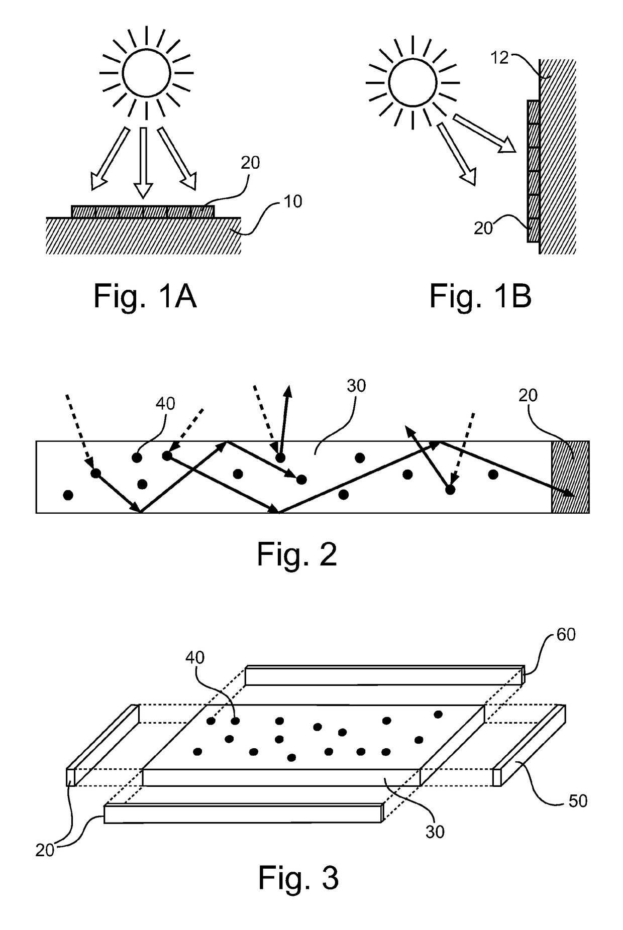
[0051]FIG. 3 shows a schematic perspective exploded view of a photovoltaic cell device with LSC according to a

[0052]The device comprises a transparent matrix or plate 30 which has a dimension in the vertical z-direction that is significantly smaller compared to the horizontal x and y dimension. In or on top of the transparent plate 30 luminophores 40 are integrated that absorb (solar) irradiation and reemit the light in all directions. To the smaller sides of the transparent plate 30 one or more solar cells 20 are attached. To other smaller sides of the matrix (an array of) one or more LEDs 50 are attached. To the remaining smaller side(s) reflective mirrors 60 may be attached. The energy storage device can be integrated on the back side of the solar cell 20, LED (array) 50, or mirrors 60. The energy storage device may also be a separate component, not integrated in the device.

[0053]The invention disclosed here combines the energy generating capability of LSCs with a lighting applic...

second embodiment

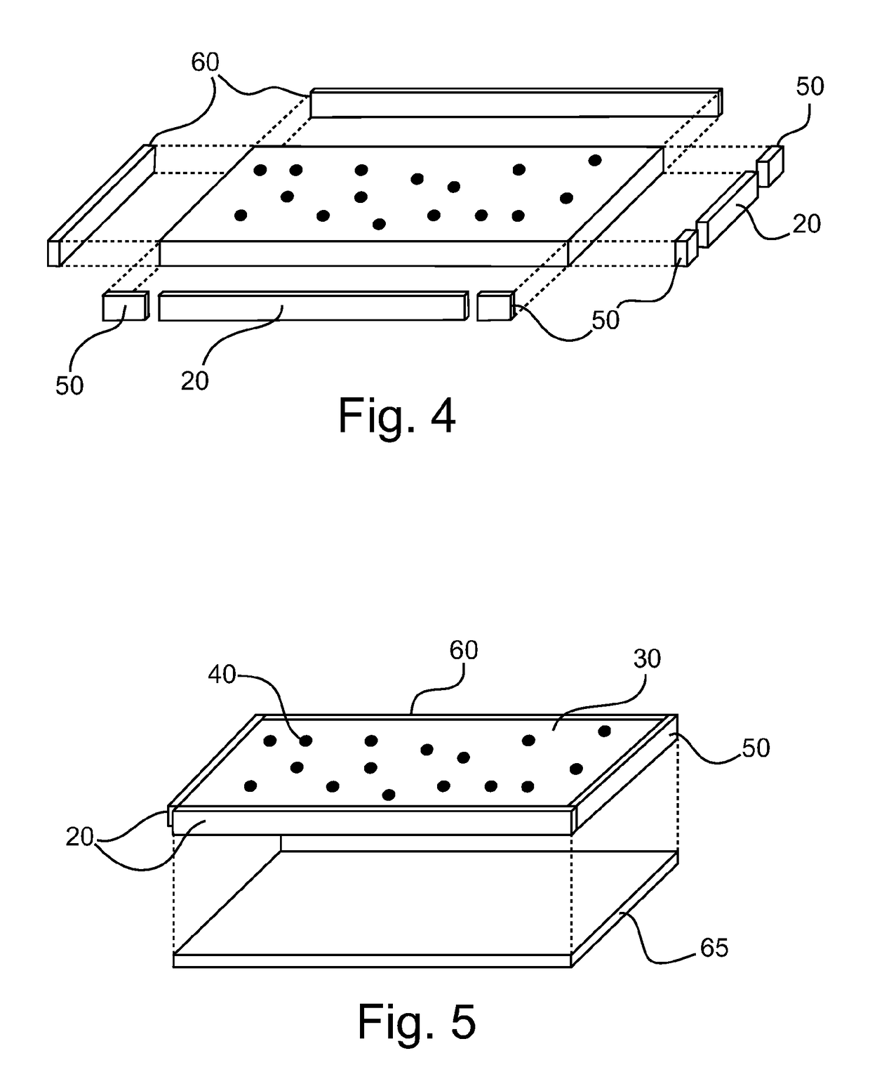
[0060]FIG. 4 shows a schematic perspective exploded view of a photovoltaic cell device with LSC according to a

[0061]The LEDs 50 can have a relatively small area and therefore need not to cover one entire side surface of the transparent plate 30. Therefore, in the second embodiment, the LEDs 50 are placed next to either the solar cells 20 or the mirrors 60. In FIG. 4, an exemplary case is shown where the LEDs 50 are placed next to the solar cells 20.

[0062]Depending on the geometry of the transparent plate 30, the efficiency of the solar cells 20, the efficiency and size of the LED 50, and type of application, an optimum can be found in the number of each of these components, and at which sides they are mounted. It may for example be preferred to have the solar cells 20 on the other side of the LEDs 50, or in another embodiment to have the mirrors 60 on the other side of the LEDs.

third embodiment

[0063]FIG. 5 shows a schematic perspective partially exploded view of a photovoltaic cell device with luminescent solar concentrator according to a

[0064]In the third embodiment, depending on the application (e.g. for a non-transparent lamp), it is preferred to also have a back-mirror 65 placed on the bottom (or upper) side of the device, as shown in FIG. 5. In this manner, the (solar) irradiation that is not absorbed by the transparent plate 10 is reflected back into the transparent plate 10 again, where it has another chance to be absorbed. In addition, during the LED operation mode, light emitted by the luminophores 40 can only escape from one side of the transparent plate 30.

[0065]In a specific implementation, the matrix of the transparent plate 30 could be transparent over a range between e.g. 400 and 900 nm, and preferably over a range of e.g. 300-1000 nm. It may consist of a polymer, or a mixture of polymers, such as methylmethacrylate (PMMA), laurylmethacrylate (LMA), 2-hydro...


PUM


Abstract

The present invention relates to a photovoltaic cell device with combined energy conversion and lighting option and a method a controlling such a device. It comprises a responsive element, a reflector or a light source for changing light absorption and thus appearance of photovoltaic cells (e.g. solar panel). It is also possible to combine the responsive element or the reflector with light source(s) providing extra illumination. When combined with a sensor and control unit, ambient intelligent solar panels and ambient intelligent lighting systems can be obtained. A combination of a luminescent solar concentrator (LSC) and light-emitting device is also possible, where an energy storage device is charged by a photovoltaic cell upon irradiation. The energy storage powers one or more light sources which are coupled to the sides of the luminescent plate. The light emitted by the light sources is coupled into the plate and (partly) converted by the luminescent plate. This results in a plate that homogeneously emits light.

Description

FIELD OF THE INVENTION[0001]The present invention generally relates to a photovoltaic cell device comprising a cell or cell assembly arranged to convert energy of sunlight or any other light source into electrical energy by the photovoltaic effect. Cell assemblies can be used to make solar panels, solar modules, photovoltaic arrays, solar concentrators, or the like.BACKGROUND OF THE INVENTION[0002]Renewable green energy sources such as photovoltaic or solar cells are gaining more importance. There is a growing demand for clean sources of energy. Such photovoltaic cells harvest energy light during the day and are idle at night. They can be combined with solar concentrators or they can be exposed directly to sunlight. A good place to position such solar panels is the front surface of a building facing the south or on the ground. However, at night, because there is less light available and light absorption of the solar cells is high, such a building covered with solar panels look very ...

Claims


Application Information

Patent Timeline
Patent Type & Authority Patents(United States)
IPC IPC(8): H01L31/0232F21S9/03G09F13/22H01L31/055G09F13/20H01L31/054F21V8/00F21V33/00F21Y105/00F21Y115/10F21Y115/30
CPCH01L31/02322F21S9/03G09F13/20G09F13/22H01L31/055H01L31/0547Y02E10/52F21V33/006F21Y2105/00F21Y2115/10F21Y2115/30G02B6/0095
Inventor VAN BOMMEL, TIESHIKMET, RIFAT ATA MUSTAFAKOOLE, ROELOFDE BOER, DIRK KORNELIS GERHARDUS
Owner SIGNIFY HLDG BV
Why Eureka
Try Eureka