X-ray detector and X-ray system

a detector and x-ray technology, applied in the field of x-ray system and x-ray detector, can solve the problems of spatial resolution deterioration, signal blur over neighboring pixels, etc., and achieve the effect of improving noise performan

Active Publication Date: 2018-03-06
FRAUNHOFER GESELLSCHAFT ZUR FOERDERUNG DER ANGEWANDTEN FORSCHUNG EV
View PDF31 Cites 2 Cited by
  • Summary
  • Abstract
  • Description
  • Claims
  • Application Information

AI Technical Summary

Benefits of technology

[0014]Embodiments of the present invention are based on detector modules to be arranged on an arc of a circle at a flexibly adjustable radius of curvature. Due to the circular arc arrangement of the detector modules, all the normals to surface thereof can meet in a reference region, exemplarily at the location of the radiation sources, which is equivalent to focusing the detector modules onto the radiation source. Thus, the X-radiation will impinge on the individual detector modules perpendicularly and an influence (blurring) of neighboring pixels as a consequence of oblique transmission can be minimized. The radius of curvature adjustable by means of manipulation means, such as, for example, an actuator, allows the respective detection region or the respective normal to surface to be orientated to the radiation source specifically for each detector module. The adjustability offers the advantage that exact focusing may even be achieved when the focus-detector distance has been changed, exemplarily as a consequence of a varied measuring setup. Additionally, with a bent X-ray detector arrangement, the radiation dose of the X-radiation incident on the individual detector modules is not dependent on which detector module the X-radiation impinges on, since the distance between the radiation source and each detector module will be the same, due to the circular arrangement, when the detector modules are oriented to the radiation source or a focal spot of the radiation source. Thus, apart from the spatial resolution, the noise performance may at the same time be improved to a constant good value over the entire detection region.

Problems solved by technology

Due to the oblique transmission through the sensor layer, the spatial resolution is deteriorated or, more precisely, a signal is blurred over neighboring pixels.

Method used


Image

  • X-ray detector and X-ray system
  • X-ray detector and X-ray system
  • X-ray detector and X-ray system

Examples


Embodiment Construction

[0026]Before embodiments will be discussed in greater detail with reference to the Figures, it is pointed out that same elements or elements of equal effect are provided with same reference numerals such that the description thereof is mutually applicable or exchangeable.

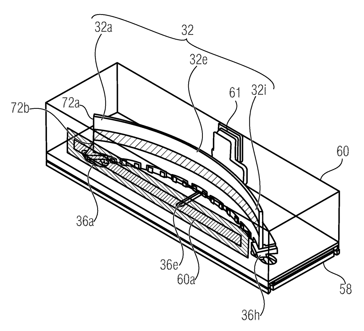
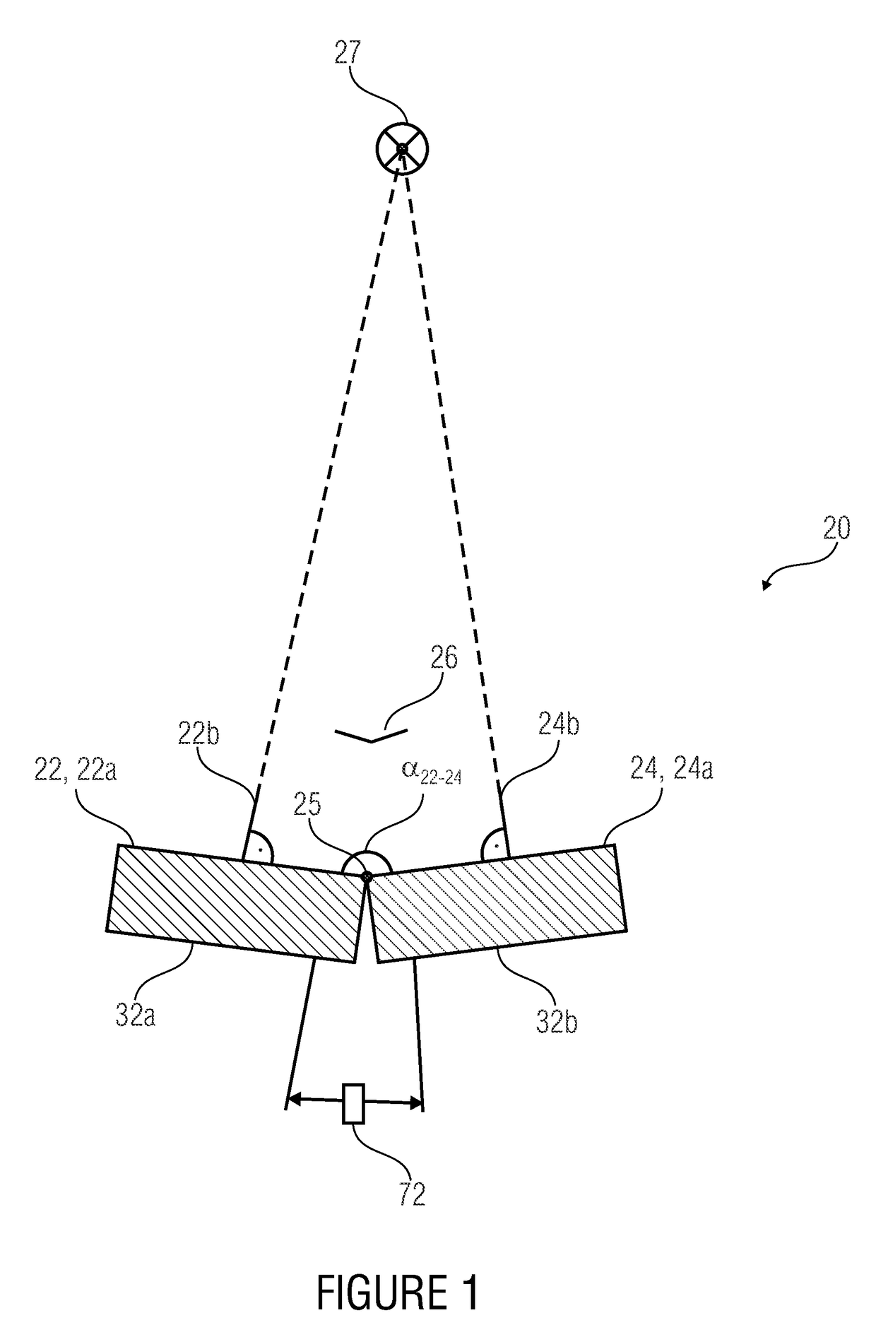
[0027]FIG. 1 shows an X-ray detector 20 comprising a first detector module 32a and a second detector module 32b with which manipulation means 72 is engaged for exactly positioning same. The first detector module 32a comprises a first detection region 22a arranged in a first detection plane 22, the second detector module 32b comprises a second detection region 24a arranged in a second detection plane 24, the two detection regions 22a and 24a being arranged such that they are neighboring or even directly abutting onto each other and facing incident X-radiation 26 emitted by a radiation source 27. The two detector modules 32a and 32b are at an angle relative to each other (cf. angle α22_24) or arranged on a circular pa...


PUM


Abstract

An X-ray detector has a first detector module, a second detector module and manipulation means. The first detector module includes a first detection region arranged in a first detection plane, the second detector module includes a second detection region arranged in a second detection plane, which is adjacent to the first detection region. The manipulation means is configured to orient the first detection plane of the first detector module and the second detection plane of the second detector module to each other such that a first normal to surface of the first detection plane and a second normal to surface of the second detection plane intersect within a reference region.

Description

CROSS-REFERENCE TO RELATED APPLICATIONS[0001]This application is a continuation of International Application No. PCT / EP2013 / 060122, filed May 16, 2013, which is incorporated herein by reference in its entirety, and additionally claims priority from German Application No. 102012208305.7, filed May 16, 2012, which is also incorporated herein by reference in its entirety.BACKGROUND OF THE INVENTION[0002]Embodiments of the present invention relate to an X-ray system, an X-ray detector and, in particular, to an X-ray detector comprising an adjustable radius of curvature.[0003]X-ray detectors, such as, for example, CCD sensors comprising scintillators, are included in X-ray systems in order to detect an absorption profile which results from transmission of an object by X-radiation and allows drawing conclusions as to a density distribution of the object.[0004]FIG. 7 shows such an X-ray system comprising a radiation source 10 and a detector 12 which is arranged spaced apart from the radiat...

Claims


Application Information

Patent Timeline
Patent Type & Authority Patents(United States)
IPC IPC(8): A61B6/06A61B6/00H01L27/146H01L27/148G01T1/24
CPCA61B6/447A61B6/4233A61B6/4291H01L27/14601H01L27/14636H01L27/14806G01T1/243A61B6/4266A61B6/4452A61B6/587A61B2562/164
Inventor HOFMANNHEBELE, STEFANSCHLECHTER, THOMAS
Owner FRAUNHOFER GESELLSCHAFT ZUR FOERDERUNG DER ANGEWANDTEN FORSCHUNG EV
Why Eureka
Try Eureka