Phase-locked loop circuit, recording-and-reproducing apparatus, and electronic appratus

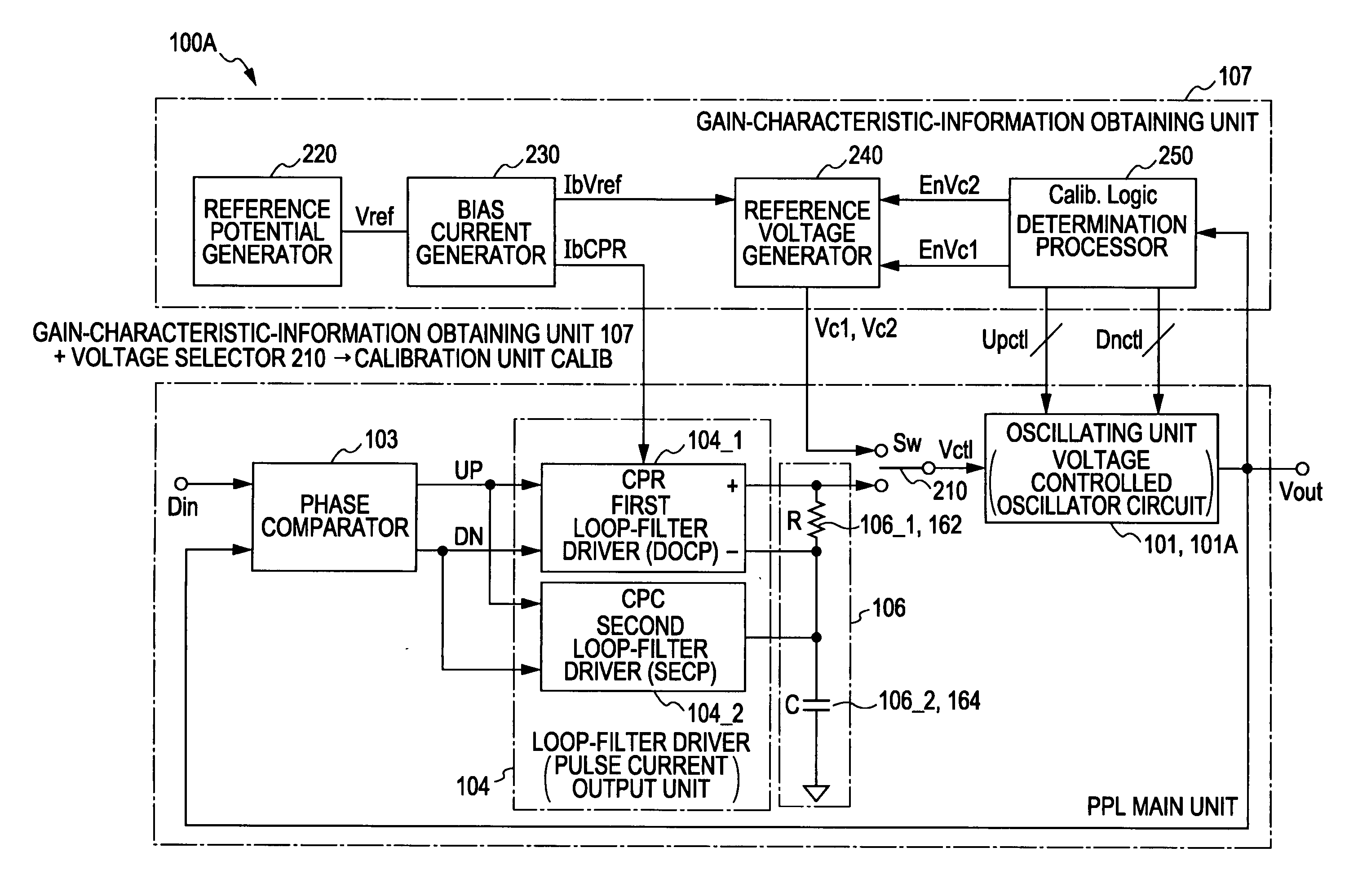
a phase-locked loop and loop circuit technology, applied in the field of phase-locked loop circuits, can solve the problems of noise performance, difficult to design correction circuits, difficult to compensate for variations by controlling the absolute value of gain, etc., to achieve the effect of facilitating the operation of adjusting the natural frequency and the damping factor independently of each other, and reducing the difficulty of design correction circuits

Inactive Publication Date: 2010-02-04
SONY CORP
View PDF8 Cites 23 Cited by
  • Summary
  • Abstract
  • Description
  • Claims
  • Application Information

AI Technical Summary

Benefits of technology

[0033]In addition, preferably, an improvement in terms of one or more of the noise performance, the circuit scale, and the design and verification processes is also provided. More preferably, a structure which allows calibrations for variations and temperature characteristics of elements (in particular, resistor elements) included in a loop filter is provided. More preferably, a structure in which the noise performance, the circuit scale, the ease of calibration, and the design and verification processes are balanced is also provided.
[0034]In the structure according to an embodiment of the present invention, a loop filter unit includes a series circuit of a resistor circuit and a capacitor circuit. An end of the capacitor circuit opposite the resistor circuit is connected to a reference point. The resistor circuit and the capacitor circuit are driven by two pulse-current output units. One of the pulse-current output units provides a single-end output, and the other provides a differential output. When one of the pulse-current output units provides a single-end output and the other provides a differential output, voltages at both ends the resistor circuit and the capacitor circuit are independent of each other. Therefore, the operation of adjusting the natural frequency and the damping factor independently of each other can be facilitated. In addition, a calibration unit is provided for correcting an oscillation gain of an oscillating unit. Thus, calibration can be performed in accordance with the characteristic variation of the oscillating unit and the temperature variation.
[0035]According to an embodiment of the present invention, a new phase-locked loop circuit is provided which is capable of varying the natural frequency and the damping factor without switching between the resistor circuits or the capacitor circuits, as in Patent Document 1. In addition, since the calibration unit which corrects the oscillation gain of the oscillating unit is provided, calibration can be performed in accordance with the characteristic variation of the oscillating unit and the temperature variation. When one loop filter is driven in a single-end mode and the other loop filter in a differential mode, voltages at both ends of the resistor circuit and the capacitor circuit are independent of each other. Therefore, the natural frequency and the damping factor can be easily calibrated.

Problems solved by technology

Therefore, it is difficult to design the correction circuits.
However, in view of the device characteristics and the circuit structure, it is difficult to compensate for the variations by controlling the absolute value of the gain.
In addition, there is also a problem of noise performance.
In addition, there is also a problem of calibration method.

Method used


Image

  • Phase-locked loop circuit, recording-and-reproducing apparatus, and electronic appratus
  • Phase-locked loop circuit, recording-and-reproducing apparatus, and electronic appratus
  • Phase-locked loop circuit, recording-and-reproducing apparatus, and electronic appratus

Examples


Embodiment Construction

[0055]An embodiment of the present invention will be described in detail below with reference to the accompanying drawings. Functional elements corresponding to different examples or modifications are denoted by reference numerals with capital letters A, B, C, . . . , at the end to distinguish them from each other, and the capital letters are omitted when it is not necessary to distinguish them from each other. This also applies to the drawings.

Outline of Read / Write Apparatus

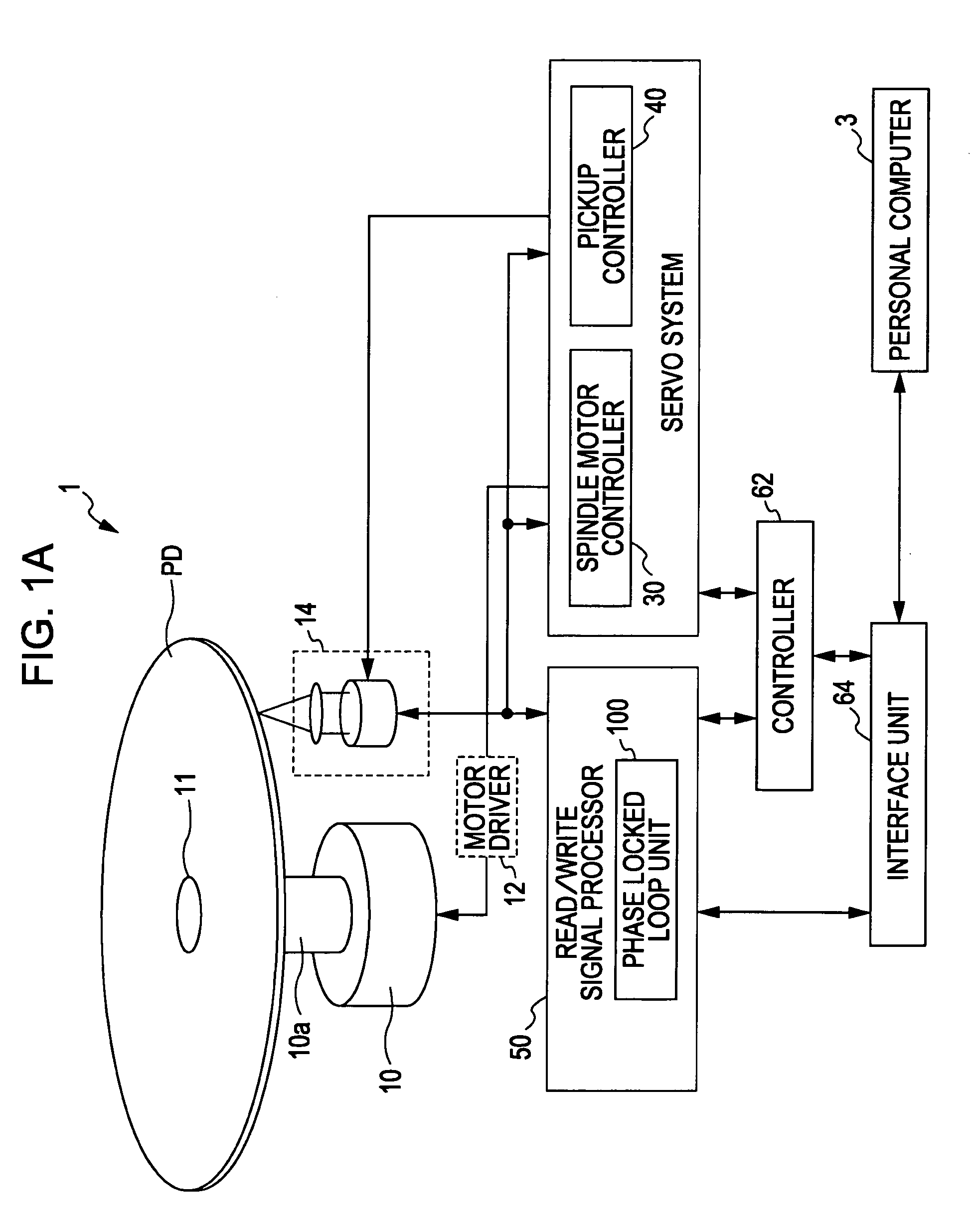
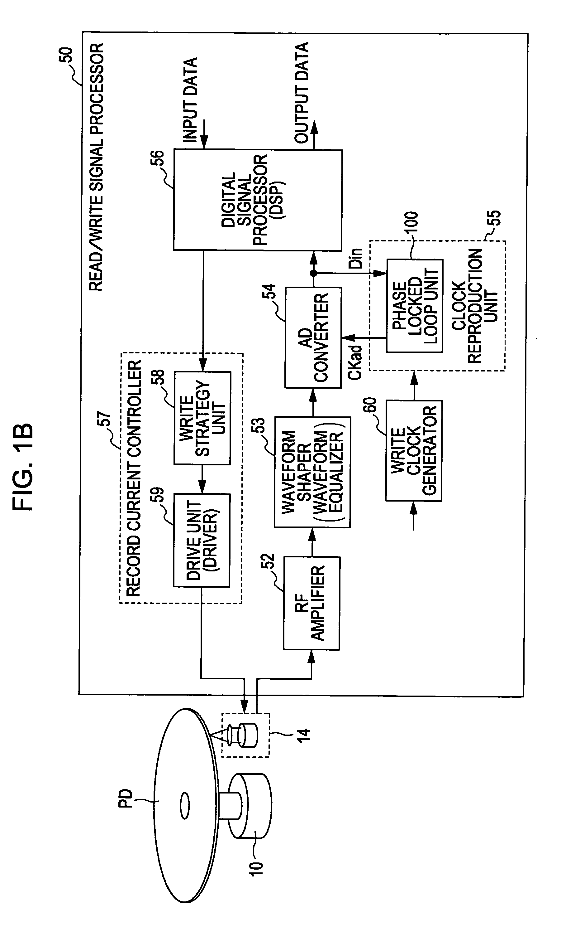
[0056]FIG. 1A is a block diagram illustrating a read / write apparatus (optical disk apparatus) according to the embodiment. The read / write apparatus is an example of an electronic apparatus including a phase-locked loop circuit.

[0057]A read / write apparatus 1 of the present embodiment includes an optical pickup 14 having a laser source for writing additional information on an optical disk PD (photo disk) or for reading the information recorded on the optical disk PD. The read / write apparatus 1 also includes a serv...


PUM


Abstract

A phase-locked loop circuit includes a phase detection unit, a loop filter unit including a series circuit of a resistor and a capacitor, first and second pulse-current output units which supply differential and single-end pulse currents corresponding to phase information to the resistor and capacitor, an oscillating unit which varies an oscillation frequency in accordance with a voltage generated at the resistor and capacitor, and a calibration unit which obtains information of an oscillation gain in actual operation and corrects an operation of the oscillating unit on the basis of a difference between the oscillation gain in actual operation and a target oscillation gain. The oscillation gain in actual operation represents a characteristic of oscillation frequency versus input signal of the oscillating unit and is obtained using predetermined oscillation control signals on the basis of a difference between actual oscillation frequencies under the oscillation control signals.

Description

BACKGROUND OF THE INVENTION[0001]1. Field of the Invention[0002]The present invention relates to a phase-locked loop (PLL) circuit used in various types of electronic apparatuses, for example, in communication apparatuses, such as a television receiver and a mobile phone, for receiving or transmitting information, or in read / write apparatuses, such as an optical disk apparatus. The present invention also relates to an electronic apparatus, such as a read / write apparatus, including the phase-locked loop (PLL) circuit.[0003]2. Description of the Related Art[0004]In general, phase-locked loop (PLL) circuits are installed in various types of electronic apparatuses, such as a communication apparatus, a transmitting-and-receiving apparatus, and an optical disk apparatus, for producing an oscillation signal with high spectrum precision or for generating a frequency-locked and phase-locked clock signal for a data signal. Examples of apparatuses including the PLL circuits include a wireless ...

Claims


Application Information

Patent Timeline
Patent Type & Authority Applications(United States)
IPC IPC(8): H03L7/099
CPCH03L7/087H03L7/0893H03L7/0898H03L2207/06H03L7/099H03L7/0995H03L7/1976H03L7/093
Inventor FUJIWARA, TETSUYAUENO, YOSUKE
Owner SONY CORP
Why Eureka
Try Eureka