
Heat integrated distillation apparatus

a distillation apparatus and heat-integrated technology, applied in distillation regulation/control, fractional distillation, separation processes, etc., can solve the problems of large amount of energy consumed, inability to obtain product, and inability to form pipe arrangements, etc., to achieve convenient maintenance of the apparatus, high energy efficiency, and optimized feed stages

Active Publication Date: 2018-03-06
TOYO ENG CORP
View PDF20 Cites 10 Cited by
  • Summary
  • Abstract
  • Description
  • Claims
  • Application Information

AI Technical Summary

Benefits of technology

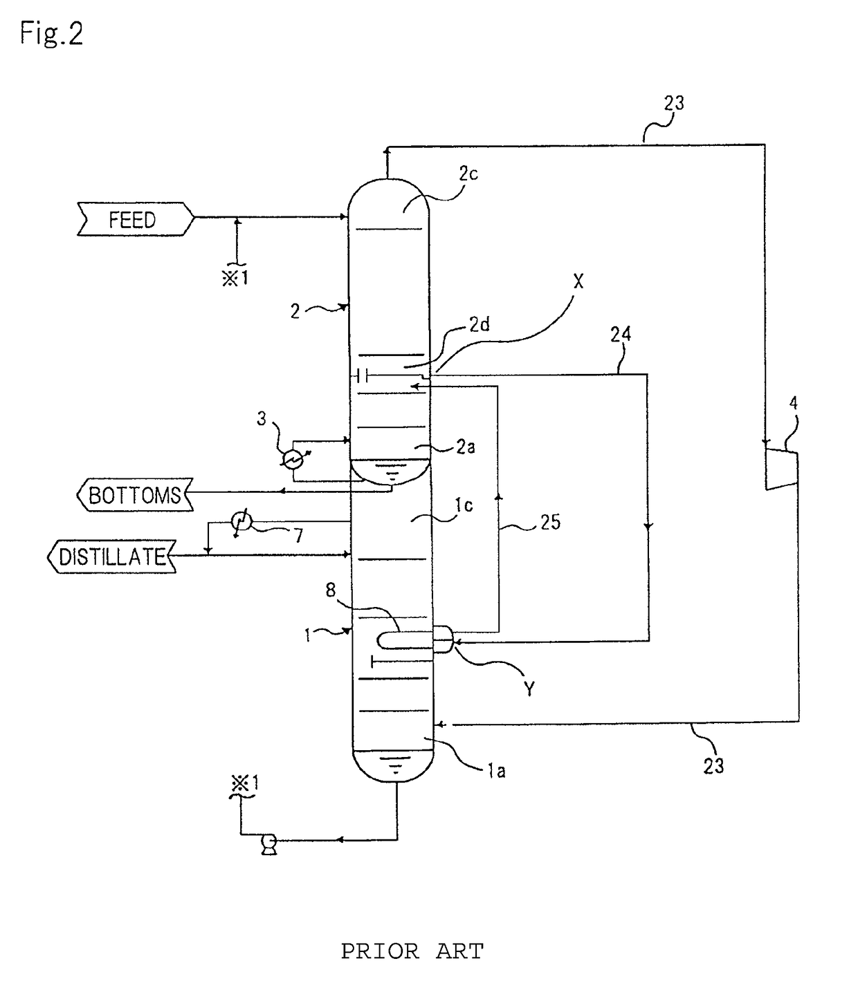
[0041]An object of the present invention is to improve the aforementioned points in both of the apparatus configuration examples of FIGS. 2 and 3 as described above, and achieve further energy saving.
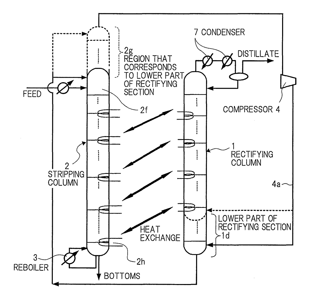
[0052]In the above aspect, the high-temperature vapor by the compressor is introduced into the heat exchanger which is located in the lower part (not limited to the lowermost stage) of the low-pressure column, and the fluids which flow out from the heat exchanger are introduced to the lower part of the high-pressure column, whereby heat is provided to the lower part (not limited to the lowermost stage) of the low-pressure column, and the fluids to be introduced to the lowermost part of the high-pressure column can be cooled. The heat transfer system (side heat exchanging section) using the second and the third pipes and the heat exchanger in the low-pressure column is configured as if a side condenser is installed at the stage of the lowermost part of the high-pressure column, and a side reboiler is installed at the stage of the lower part (not limited to the lowermost part) of the low-pressure column. Thus, as compared with a distillation apparatus that does not include the above described heat transfer system, the amount of heat that is removed can be reduced more at the condenser, and the amount of heat that is supplied can be reduced more at the reboiler.
[0053]In particular, the above described heat transfer system which enables heat exchange between the low-pressure column lower part and the high-pressure column lower part is configured to introduce the high-pressure vapor from the compressor directly into the heat exchanger which is provided at the low-pressure column and to thereby feed the fluids condensed in the heat exchanger into the high-pressure column. That is to say, the configuration does not need a liquid head as in the apparatus example of FIG. 2, or the pressure loss is not required as in the apparatus example of FIG. 3. Therefore, energy saving performance can be improved because the liquid head and the pressure loss are not needed. Further, the region corresponding to the lower part of the rectifying section (rectifying section corresponding portion) can be operated due to the pressure of the low-pressure column which is lower than the pressure of the high-pressure column, and therefore, as compared with the configurations of FIGS. 4 to 6, the relative volatility in the rectifying section corresponding portion becomes larger. Thus, the energy (heat amount) itself which originally becomes necessary for a separating process can be reduced.
[0055]The rectifying section and the stripping section, or the high-pressure column and the low-pressure column are configured by using the trayed sections or packed bed sections similar to those of a general distillation apparatus. Hence, the apparatus can deal with side cutting or multi-feed stream without the need for any improvement, and it is possible to easily perform maintenance of the apparatus. For the same reason, the number of stages of the rectifying section or the stripping section can be freely set, and the feed stage can be optimized.
[0057]According to the present invention, energy efficiency is high, side-cutting and setting of a feed stage position can be easily dealt with, and maintenance of the apparatus is easy. Further, the apparatus of the present invention has a structure in which a degree of freedom in design is high, and hence can be easily accepted by the user side.
[0058]In addition, according to the present invention, the aforementioned points in both of the apparatus configuration examples of FIGS. 2 and 3 are improved, and further energy saving can be achieved.

Problems solved by technology

Distillation separation is a unit operation widely applied to industrial processes in general, but consumes a large amount of energy.
1) The product cannot be obtained with side-cut stream.
As a result, no pipe arrangement can be formed to withdraw any intermediate distillate product from the inner pipe of each tube unit.
2) The feed stage where feed stream is provided cannot be optimized.
5) Maintenance of the apparatus is difficult.
This disables complete access to the desired tube unit, and maintenance thereof cannot be carried out.
However, if outlet pipe 4a of compressor 4 is directly connected to the heat exchanging section located at the lowermost position of the rectifying section without being directly connected to the lowermost portion of the rectifying section, there will not be any gas in lower part 1d, which is located below this, of the rectifying section, and therefore, distillation operation which has liquid-vapor equilibrium as the principle of separation is not established.
Therefore, the apparatus which uses this method of connection cannot be realized.

Method used


Image

  • Heat integrated distillation apparatus
  • Heat integrated distillation apparatus
  • Heat integrated distillation apparatus

Examples


Embodiment Construction

[0099]A heat integrated distillation apparatus according to the present invention has a basic feature in which a column shell (low-pressure column) that is the result of adding a region used as a stripping section extending in a vertical direction, and a region (or a rectifying section corresponding portion) that corresponds to a region locating below a side heat exchanging section at the lowermost stage among side heat exchanging sections installed in the rectifying section, and a column shell (high-pressure column) which includes a region, except for the aforementioned region that corresponds to the rectifying section of the rectifying section extending in the vertical direction, are separately provided, and the low-pressure column is located above as seen from the high-pressure column. A general distillation apparatus, which is not an internally heat integrated distillation apparatus, includes a column that is built in the vertical direction and that has a column bottom, a trayed...


PUM


Abstract

A distillation apparatus of the present invention includes high-pressure column 1 corresponding to a region above a heat exchanging section located at a lowermost part of a region including a trayed section or a packed bed section, which is used as a rectifying section; and low-pressure column 2 that is located above as seen from high-pressure column 1, which integrates a region including a trayed section or a packed bed section which is used as a stripping section, with rectifying section corresponding portion 2g that corresponds to a region locating below the heat exchanging section located at the lowermost part in the rectifying section. Rectifying section corresponding portion 2g is located on top 2c of the stripping section in low-pressure column 2 so that rectifying section corresponding portion 2g continues to the stripping section.

Description

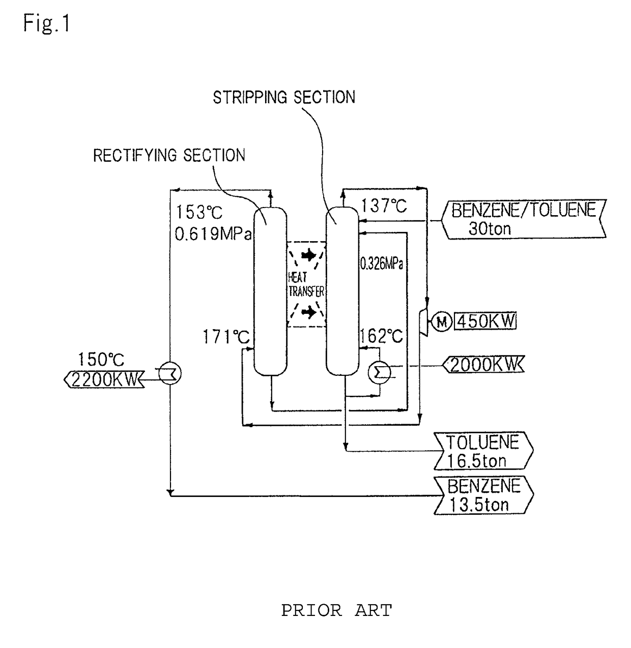
[0001]This application is based upon and claims the benefit of priority from Japanese patent application No. 2012-080525, filed on Mar. 30, 2012, the disclosure of which is incorporated herein in its entirety by reference.BACKGROUND OF THE INVENTION[0002]1. Field of the Invention[0003]The present invention relates to a distillation apparatus that carries out a distillation operation widely applied to many industrial processes, and more particularly to a heat integrated distillation apparatus.[0004]2. Description of the Related Art[0005]Distillation separation is a unit operation widely applied to industrial processes in general, but consumes a large amount of energy. In the industrial field, therefore, studies have been conducted on an energy saving distillation systems. Such studies have brought about development of a heat integrated distillation column (hereinafter, HIDiC) as a distillation apparatus that save much energy.[0006]As shown in FIG. 1, a basic system of the HIDiC has a...

Claims


Application Information

Patent Timeline
Patent Type & Authority Patents(United States)
IPC IPC(8): B01D3/14B01D3/00B01D1/28B01D3/32B01D3/42
CPCB01D3/007B01D1/28B01D3/4261B01D3/322B01D3/143B01D3/00B01D3/32
Inventor WAKABAYASHI, TOSHIHIRONAKAO, TAKATO
Owner TOYO ENG CORP
Learn More