Heat module

a heat module and heat source technology, applied in the field of heat modules, can solve the problems of affecting the cooling effect of the heat pump, so as to reduce the thickness and reduce the thickness of the heat pipe. , the effect of excellent cooling characteristi

Active Publication Date: 2018-03-06
NIDEC CORP
View PDF20 Cites 0 Cited by
  • Summary
  • Abstract
  • Description
  • Claims
  • Application Information

AI Technical Summary

Benefits of technology

[0008]According to the above preferred embodiment of the present invention, it is possible to provide a heat module having an excellent cooling characteristic and a reduced thickness, with the thickness of the heat pipe being minimized.

Problems solved by technology

Small and high-performance electronic devices, such as, for example, notebook PCs, produce a large amount of heat at CPUs and the like inside cases thereof.
Due to a reduction in the thickness of the heat pipe, the capillary structure may become deformed to impede travel of the working fluid.

Method used


Image

  • Heat module
  • Heat module
  • Heat module

Examples


Embodiment Construction

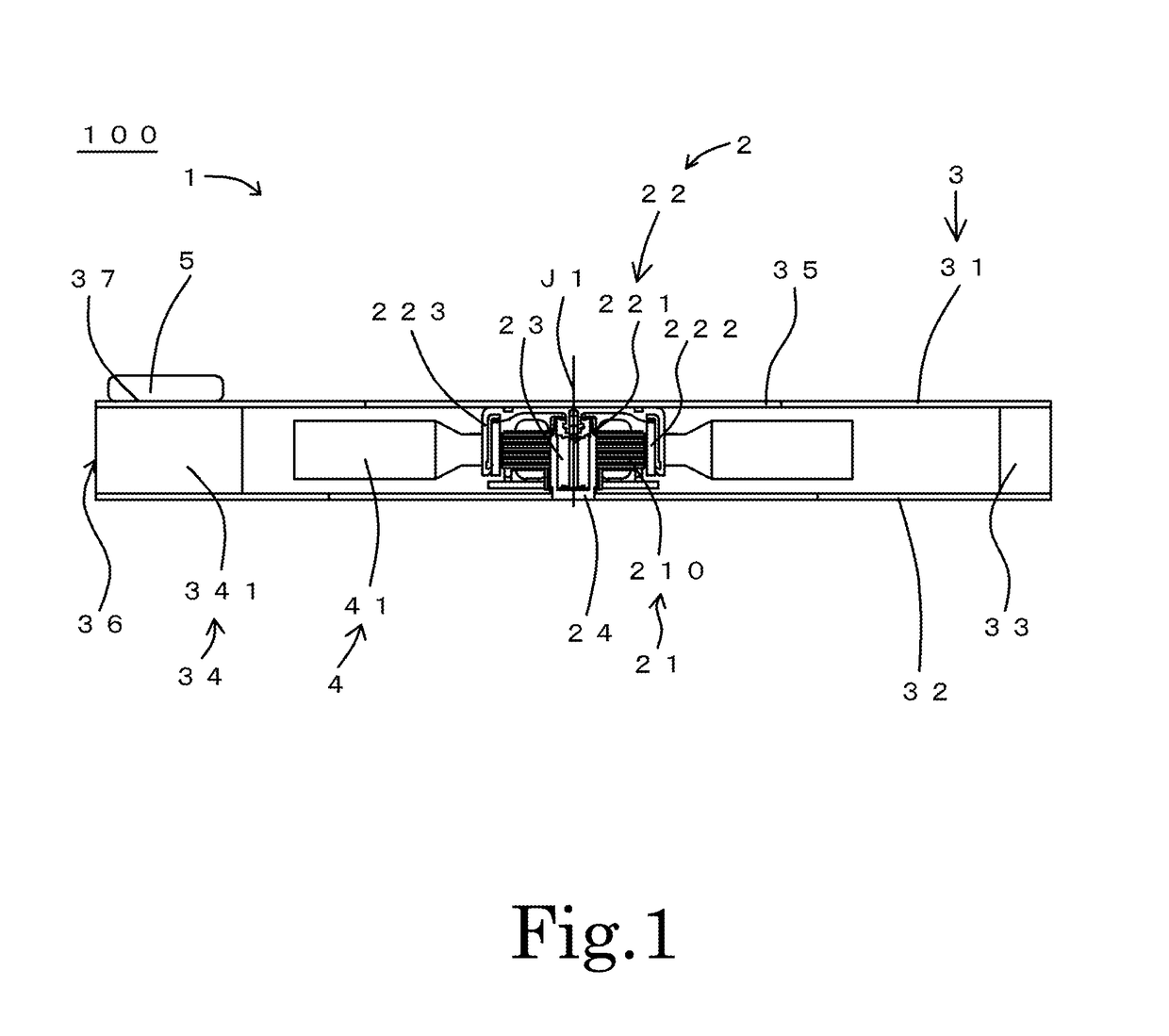
[0016]It is assumed herein that an upper side and a lower side in an axial direction parallel to a central axis of a fan 1 of a heat module 100 in FIG. 1 are referred to simply as an upper side and a lower side, respectively. Note that a vertical direction assumed herein may not necessarily correspond with a vertical direction of the heat module 100 when the heat module 100 is actually installed in a device. It is also assumed herein that a circumferential direction about the central axis is referred to simply by the term “circumferential direction”, “circumferential”, or “circumferentially”, and that radial directions centered on the central axis are referred to simply by the term “radial direction”, “radial”, or “radially”.

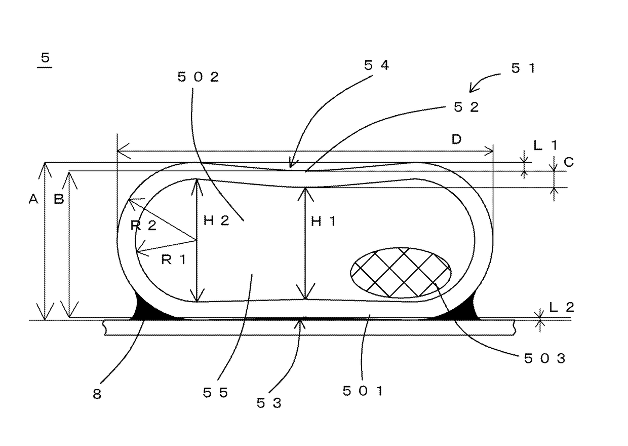
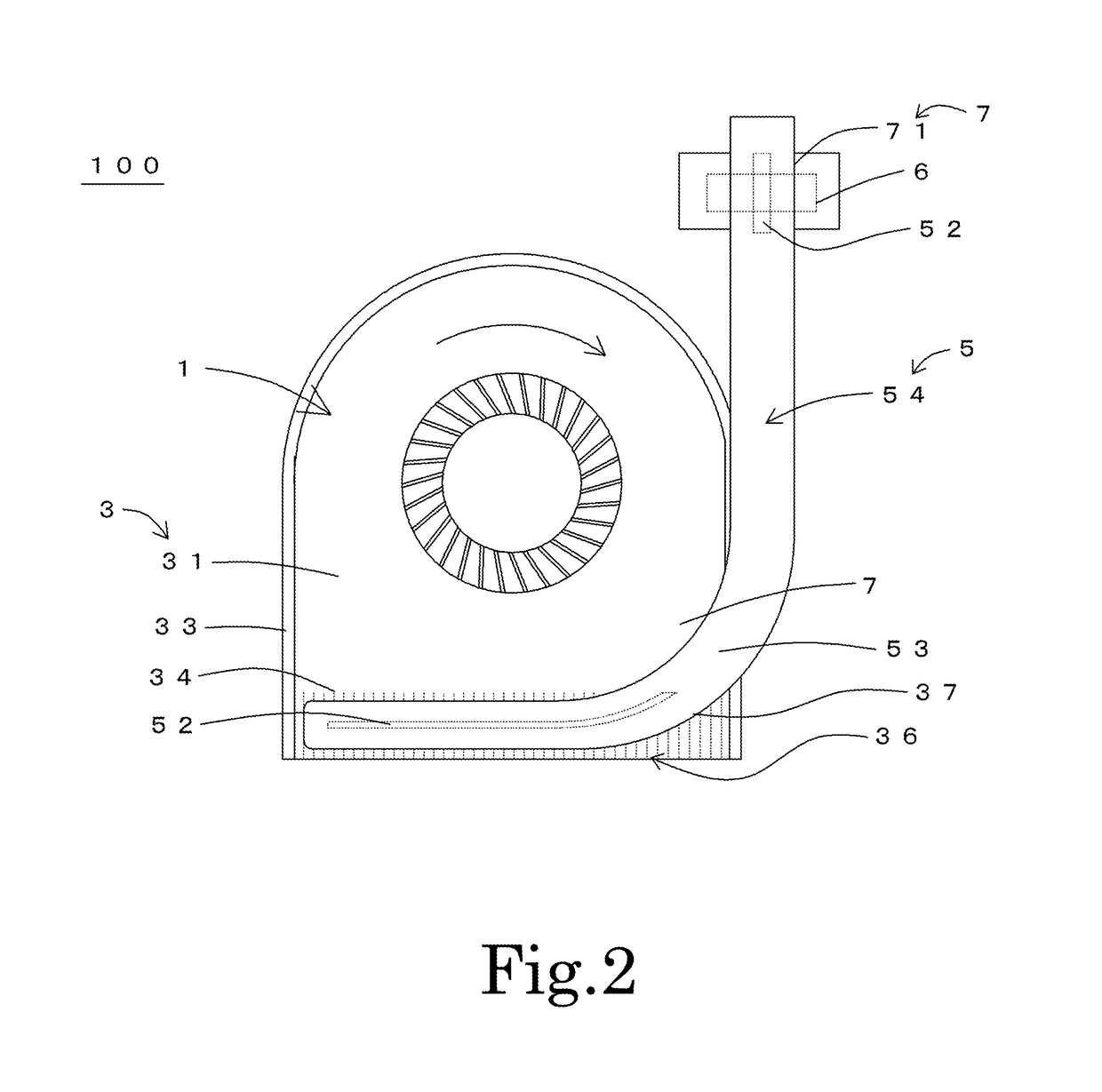
[0017]FIG. 1 is a cross-sectional view of a heat module 100 according to a first preferred embodiment of the present invention. The heat module 100 includes a fan 1 arranged to blow air in a predetermined direction, and a heat pipe 5 arranged to be in thermal co...


PUM


Abstract

A heat module includes a fan and a heat pipe. A flat portion of the heat pipe includes a recessed portion being recessed toward a center of the heat pipe in a cross section. A heat receiving portion arranged between the heat source and the heat pipe includes a heat source contact portion arranged to be in thermal contact with the heat pipe. In at least a portion of the heat pipe which extends between a portion of the heat pipe which is in thermal contact with the fan contact portion and a portion of the heat pipe which is in thermal contact with the heat source contact portion, a difference between a maximum axial height of the heat pipe and a minimum axial height of a portion of the heat pipe where the recessed portion is defined is smaller than a wall thickness of the recessed portion.

Description

BACKGROUND OF THE INVENTION[0001]1. Field of the Invention[0002]The present invention relates to a heat module. In particular, the present invention relates to a heat module installed in an electronic device, such as, for example, a personal computer (PC).[0003]2. Description of the Related Art[0004]Small and high-performance electronic devices, such as, for example, notebook PCs, produce a large amount of heat at CPUs and the like inside cases thereof. This makes it important to take measures against the heat. One common measure against the heat is to install blower fans inside the cases to discharge the heat. In a common heat module in which a heat source and a heat sink are arranged to be away from each other, the heat source and the heat sink are connected to each other through a heat pipe. Meanwhile, in recent years, electronic devices, such as the notebook PCs, have been becoming thinner and thinner, and there has been a demand for a reduction in the thickness of heat modules....

Claims


Application Information

Patent Timeline
Patent Type & Authority Patents(United States)
IPC IPC(8): F28D15/00F28D15/02G06F1/20
CPCF28D15/0233G06F1/203F28D15/0275
Inventor TAMAOKA, TAKEHITOFUKUSHIMA, KAZUHIKOHATANAKA, KOJI
Owner NIDEC CORP
Why Eureka
Try Eureka