Optical fiber cable installation in a pressure sewerage

a technology of optical fiber cable and pressure sewerage, which is applied in the direction of cables, cables, instruments, etc., can solve the problems of not being able to introduce a robot into an existing pressure sewer, not being able to simply open the pressure sewer, and too little flow in a normal sewer

Active Publication Date: 2018-03-06
JELCER IP
View PDF11 Cites 10 Cited by
  • Summary
  • Abstract
  • Description
  • Claims
  • Application Information

AI Technical Summary

Benefits of technology

[0012]The invention is also based on the fact that a cable passage not only functions as passage for the cable from inside to outside and vice versa, but also that, owing to the cable passages, the location of the cable inside the pipe can be better controlled. The embodiments of the medium conduit according to the invention are highly suitable for controlling and modifying the location of the cable in the pipe.
[0013]The manifold comprises a second cable passage in addition to a first cable passage, wherein a single piece of cable lies in each cable passage. This ensures that the cable is better guided, whereby there is less risk of breakage.
[0016]The releasable pipe segment may well be optically transparent, so as to allow visual inspection during release i.e. removal of the releasable pipe segment from the manifold. This visual inspection may minimize the risk of damaging the cable unintentionally. Most practically would be a segment that is fully optically transparent, but a segment with a window constitutes an alternative.
[0021]Suitably, the manifold can be rotated between a protected position and a service position. The protected position is particularly a position wherein the exposed cable is protected against damage during excavation work. The risk for damage is considerable, since excavation work is usually carried out by people not aware of the presence of the cable passage and / or cable. Mistakes are mede here in positioning during excavation work and use is made of auxiliary means which do not make allowance for the vulnerability of a cable, in particular a glass fibre cable.
[0022]In a suitable embodiment of the medium conduit the first cable passage is provided with a cable tensioner for tensioning a portion of the cable extending in the medium conduit from the first longitudinal position. A portion of the cable can hereby be tensioned. Such a portion extends for instance over a distance of 50 meters to 1 kilometer. It is not inconceivable for loops to occur or for play to occur during drawing of the cable in the pipe through said portion, for instance in bends. These loops are removed by tensioning the cable, so greatly reducing the risk of blockages. The portion of the cable for tensioning extends particularly from a first house connection to a previous or subsequent house connection, or the first or second point. The portion of the cable for tensioning can lie upstream as well as downstream of the first longitudinal position. During tensioning of a portion of the cable between a first and a second house connection the cable is typically first secured to the first house connection, then pulled taut and subsequently secured to the second house connection.
[0034]The invention preferably makes use of a pulling member at the outer end of the cable which provides for buildup of liquid pressure if necessary. This pulling member is also referred to as a liquid pressure generator. This liquid pressure generator has the particular purpose of building up liquid pressure in order to push aside or circumvent possible obstacles. This does however also make it possible for the cable to be carried along substantially by liquid without the necessity of applying additional pressure from the very start.

Problems solved by technology

This causes too little flow in a normal sewer for the purpose of draining the sewer content.
As a result it is not possible to introduce a robot into an existing pressure sewer for the purpose of laying a glass fibre cable.
Nor is it possible to simply open the pressure sewer in order to make a connection.
It is further not possible to draw the glass fibre cable to a dwelling via a house connection of the sewer, but a bridging is necessary between a connection point in the pressure sewer and a further connection to the dwelling, such as for instance an inspection well.
It is however a drawback of the known medium conduit that the cable is situated inside the medium conduit at a position which cannot be determined.
When the medium conduit transports something other than gas or liquid, such as in particular a pressure sewer, this can easily result in highly undesirable blockages.
Not only must a blockage be cleared as quickly as possible, a blockage is also difficult to trace since the conduit is located under the ground and is optically non-transparent.

Method used


Image

  • Optical fiber cable installation in a pressure sewerage
  • Optical fiber cable installation in a pressure sewerage
  • Optical fiber cable installation in a pressure sewerage

Examples


Embodiment Construction

[0040]The figures are of schematic nature. Components are not shown to scale. The same or similar elements are designated in different figures with corresponding reference numerals.

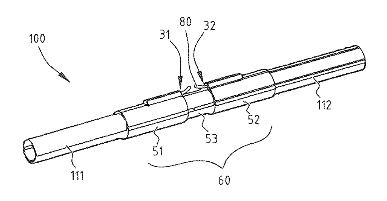
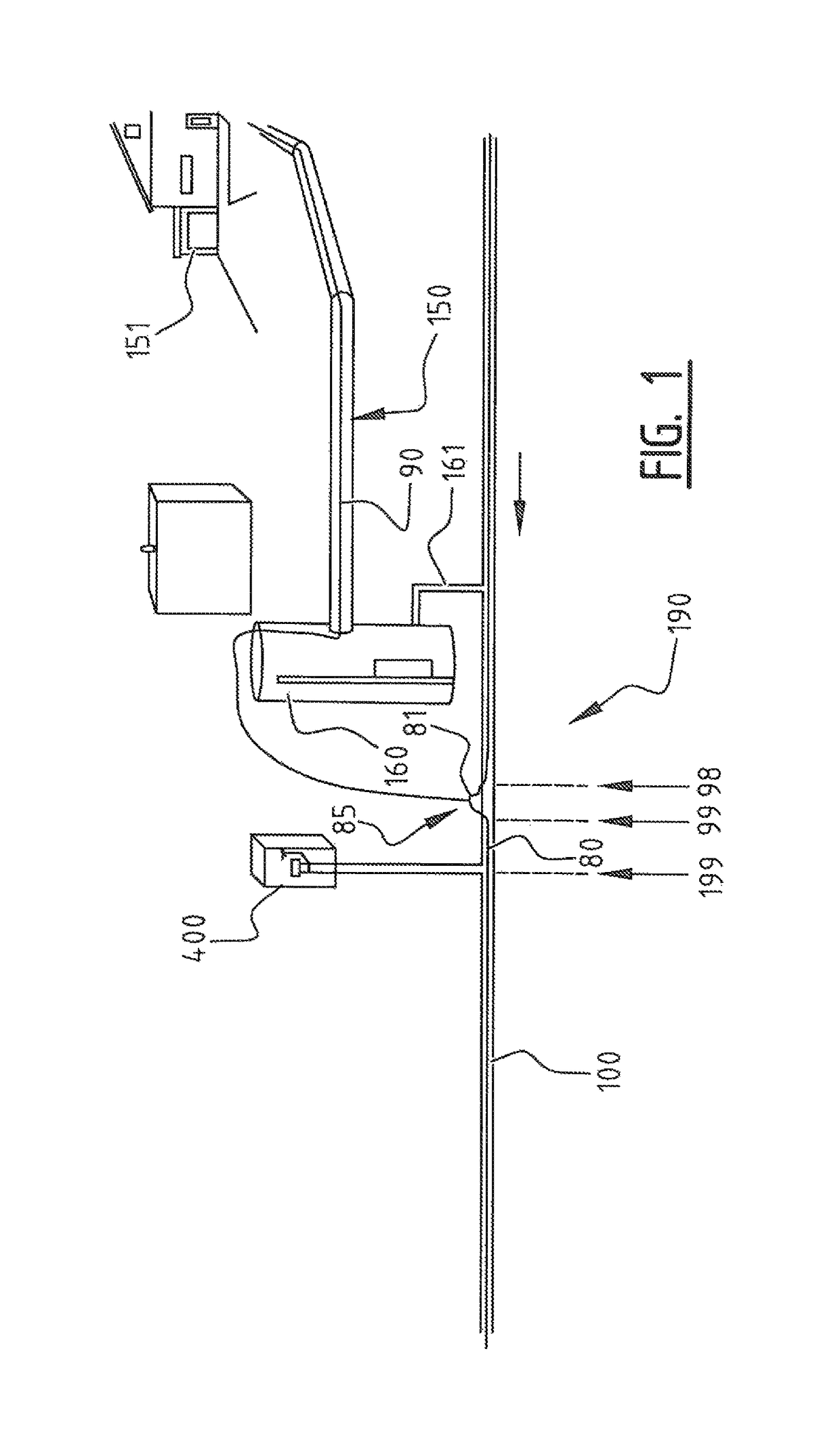
[0041]FIG. 1 is a schematic view of a house connection 190 to medium conduit 100 according to the invention. In this embodiment medium conduit 100 is a pressure sewer. Not otherwise precluded is that the invention is applied to another type of medium conduit, such as a water conduit, a district heating system based on conduits with hot water or hot air, a gas conduit. Particularly suitable is a sewer, and more precisely a pressure sewer, which as a relatively small diameter. Rather than a pressure sewer, a separate corresponding medium conduit could be used, which is however not intended for use as a sewer, gas or water conduit. This may be more effective in some areas, dependent on the state of any existing sewer. The medium conduit is suitable for transporting a medium using pressure, wherein it is not ...


PUM


Abstract

The manifold is provided with a first cable passage at a first longitudinal position and a second cable passage at a second longitudinal position, wherein a releasable pipe segment is present between the first and the second longitudinal positions. It is suitable for use in a pipe, such as a pressure sewer. In use, a cable would be laid through the pipe with the manifold. Thereafter, the releasable pipe segment would be removed from neighboring pipe shells. The cable would be inserted into the cable passages, and a second pipe segment would replace the initial pipe segment.

Description

FIELD OF THE INVENTION[0001]The invention relates to the laying of a cable in a medium conduit. The invention also relates to a thus obtained medium conduit provided with a cable. The invention further relates to auxiliary means for use herein.BACKGROUND OF THE INVENTION[0002]Cables for telecommunication, such as glass fibre cables in particular, are seen as the basis of a communication network. Efficiency requires that use be made of already existing pipe systems in the ground for the purpose of laying such a new cable network. A sewer forms a very suitable pipe network here. The sewer system in cities comprises a network of main sewers running below streets to which individual house sewers or house sewer connections are connected. The main sewer has a cross-section sufficiently large for a robot, and there are sewer drains through which a glass fibre cable can be introduced into the sewer. A method for laying a glass fibre cable in such a main sewer is per se known from EP 1868020...

Claims


Application Information

Patent Timeline
Patent Type & Authority Patents(United States)
IPC IPC(8): F16L55/10G02B6/46F16L41/02G02B6/50G02B6/44H02G1/08
CPCG02B6/4459F16L41/02G02B6/4464G02B6/502H02G1/086G02B6/46Y10T137/8376G02B6/52
Inventor SPIJKER, JOHANNES GERHARDUS
Owner JELCER IP
Why Eureka
Try Eureka