Optical system for generating a pattern which changes over time for a confocal microscope

a technology of optical system and pattern, which is applied in the direction of polarising elements, impression caps, instruments, etc., can solve the problems of compact design, large mechanical motion, and relatively high mechanism cos

Active Publication Date: 2018-03-06
DENTSPLY SIRONA INC
View PDF26 Cites 7 Cited by
  • Summary
  • Abstract
  • Description
  • Claims
  • Application Information

AI Technical Summary

Benefits of technology

[0010]According to the invention, the mechanical movement is thus replaced by a fixed, special optical arrangement and at least one polarized light source, in which the polarization direction is changed. The projected pattern or projector pattern then changes as fast as the polarization direction of the light source arrangement changes. The change in the polarization direction can be carried out as quickly as desired.
[0025]As means for evaluating received signals, a filter is preferably provided whose switching frequency is synchronized with the switching frequency of the polarization direction of the light source. Preferably, the filter is realized as a lock-in amplifier. The synchronization serves to achieve an easily detectable signal during scanning.

Problems solved by technology

However, this mechanical motion has some significant disadvantages.
The mechanism requires space, which makes a compact design impossible.
The mechanism is also relatively expensive.
In particular, the accuracy of the rate of change is limited, which substantially increases the cost of the analysis.
It can even cause operational failures in the mechanical movement.
However, they are too slow for the desired scan.

Method used


Image

  • Optical system for generating a pattern which changes over time for a confocal microscope
  • Optical system for generating a pattern which changes over time for a confocal microscope
  • Optical system for generating a pattern which changes over time for a confocal microscope

Examples


Embodiment Construction

[0007]This object is achieved by an optical system and method as set forth in the claims. Advantageous developments of the invention are specified in the dependent claims.

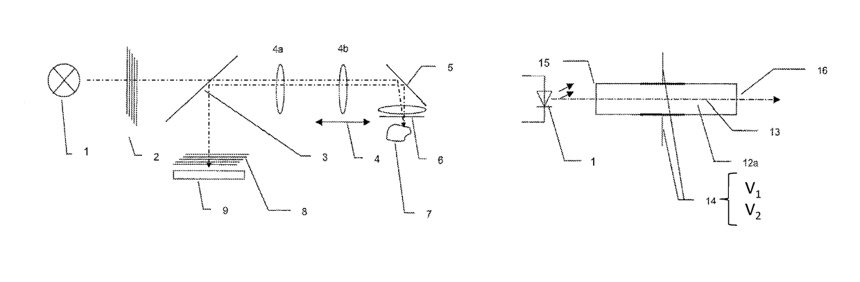
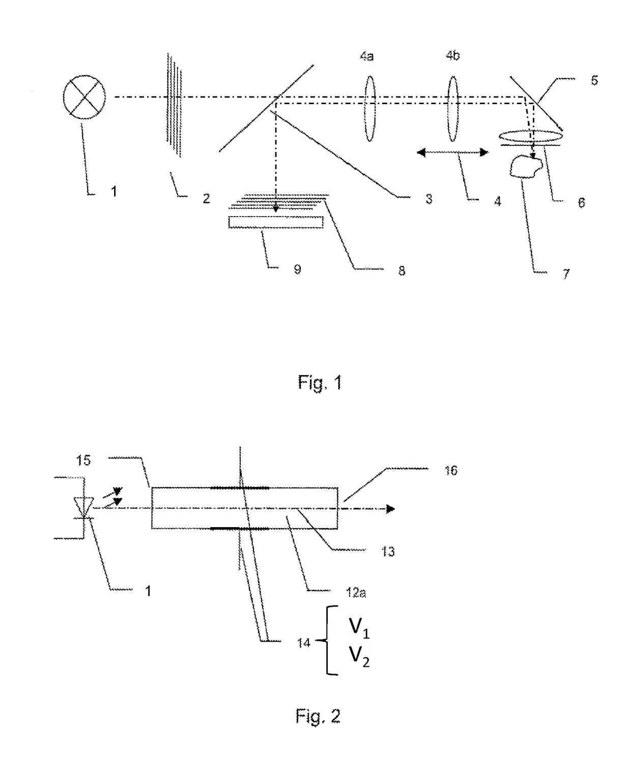
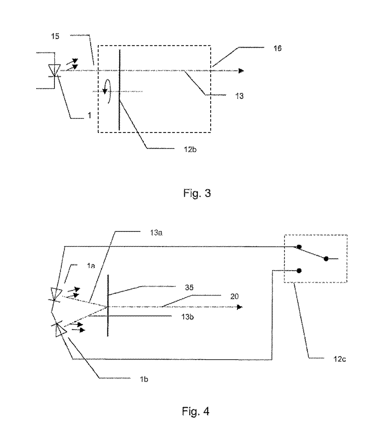
[0008]According to the invention, an optical system for a confocal microscope is provided comprising a light source arrangement from which light beams travel to an object that reflects the light beams, a beam splitter for allowing passage of the light beams proceeding from the light source arrangement in the direction of the object and for deflecting light beams reflected by the object in a focal plane in the direction of a detector with a detector pattern for detecting an image of the object and a lens arrangement between the beam splitter and the object. In particular, the light source arrangement has at least one light source and a device that switches the direction of polarization of the light beams emitted by the at least one light source to generate a changing projector pattern without moving a mask having th...


PUM

PropertyMeasurementUnit
voltageaaaaaaaaaa
transparentaaaaaaaaaa
switching frequencyaaaaaaaaaa

Abstract

The invention relates to an optical system for generating a pattern which changes over time for a confocal microscope. The system includes a light source arrangement, a beam splitter, and a lens arrangement. The beam splitter allows for passage of a light beam proceeding from the light source arrangement in the direction of an object and for deflecting the reflected light beam, reflected by the object in a focal plane, in the direction of a detector. The detector includes a detector pattern for detecting an image of the object. The lens arrangement is between the beam splitter and the object and includes: a light source that generates the light beam, and a device configured to switch a direction of polarization of the light beam to generate a changing projector pattern.

Description

TECHNICAL FIELD[0001]The invention relates to an optical system for generating a pattern which changes over time for a confocal microscope.PRIOR ART[0002]There are various types of confocal microscopes that detect a surface of an object to be scanned based on the fact that the surface is in focus. Examples of such systems are laser confocal microscopes, such as are known from US2007 / 0109559 A1, or pOFPT (=parallel Focal Point Optical Tomography), as described in the Swiss patent application 016247 / 07.[0003]In a pOFPT scanner, a moving pattern is projected onto an object to be scanned. This is advantageous because it is a simpler and more accurate signal technology to detect changing patterns than static ones. This movement is realized there such that a mask with the pattern is mechanically moved quickly. The movement is oscillating or continuous.[0004]However, this mechanical motion has some significant disadvantages. The mechanism requires space, which makes a compact design imposs...

Claims


Application Information

Patent Timeline
Patent Type & Authority Patents(United States)
IPC IPC(8): G02B21/00G02B27/10A61C9/00G02F1/01G02B5/30A61B5/107A61B5/00G02B21/36G02F1/03
CPCG02B21/0032G02B21/004G02B21/008G02B21/0028G02B21/0092G02B21/367G02B27/10G02F1/0136G02F1/0311A61C9/006G02F1/03A61B5/0066A61B5/0068A61B5/1077G02B5/3083G02B21/365
Inventor BERNER, MARKUS
Owner DENTSPLY SIRONA INC
Why Eureka
Try Eureka