Bluetooth signal receiving method and device using improved carrier frequency offset compensation

a carrier frequency offset and bluetooth technology, applied in wireless communication, phase-modulated carrier systems, wireless commuication services, etc., can solve the problems of affecting the performance of the signal, the estimated value of the carrier offset measured in the preamble interval is considerably poor, and the expected performance cannot be achieved. , to achieve the effect of improving the accuracy of the estimated value of the carrier offset, and reducing the cost of the signal

Active Publication Date: 2018-03-06
ABOV SEMICON
View PDF81 Cites 1 Cited by
  • Summary
  • Abstract
  • Description
  • Claims
  • Application Information

AI Technical Summary

Benefits of technology

[0021]Since Bluetooth Smart prioritizes costs and low power, it allows frequency drift within the maximum range of + / −50 kHz in a packet in a period of 625 Hz in order to ease the level of analog circuit design specifications. A high-sensitivity receiver requires a device for continuously tracking and removing carrier offset drifting in the access address interval 220 and the protocol data unit interval in order to reduce data loss rate.
[0024]Accordingly, the present invention is intended to provide a device and method for implementing a high-sensitivity receiver that is capable of overcoming structural problems (high jitter and a long training period) and a performance problem that occur when implementation is performed using the conventional NDA prediction technique. For this purpose, an object of the present invention is to provide a device and method for acquiring and tracking carrier frequency offset by using a “selective bit stream decision-directed” technique.
[0029]The frequency offset compensation circuit may be further configured to, when the plurality of series of bit streams satisfies the training bit pattern condition a plurality of times within a first time interval (which refers to a predetermined time range, and which may correspond to a case where a training bit pattern is repeated, such as a preamble interval), calculate the first representative value (the average, the moving average, the weighted moving average, or the like) of a plurality of effective error metrics within the first time interval and compensate the frequency proportion signal by using the first representative value. That is, when a training bit pattern appears a plurality of times within a adjacent period, the tendency of changes in offset may be tracked through the statistical processing of effective error metrics obtained from bit streams satisfying the training bit pattern condition. Examples of the statistical processing are an average technique, a sliding moving average technique, a weighted moving average technique, etc. A technique for tracking the tendency of changes in offset, such as the sliding moving average technique, may effectively extract changes in offset from bit streams present within an adjacent period, and the range of application thereof may be limited to the range of a second time interval (which is longer than the first time interval, and has a finite value) or the range of a corresponding packet.

Problems solved by technology

However, since a demand for a high-sensitivity receiver equal to or lower than −90 dBm is increasing in line with the development of implementation technology and the received signal to noise power ratio in a corresponding signal magnitude region is decreased to 10 dB or less, the reliability of the estimated value of carrier offset measured in the preamble interval is considerably poor due to the magnitude of relatively increased noise.
In this method, inter-symbol interference occurs in a filtering process, and thus a signal waveform is distorted.
Accordingly, when a typical “minimum-maximum average value” scheme is applied to tracking, great error occurs, and thus expected performance cannot be achieved.

Method used


Image

  • Bluetooth signal receiving method and device using improved carrier frequency offset compensation
  • Bluetooth signal receiving method and device using improved carrier frequency offset compensation
  • Bluetooth signal receiving method and device using improved carrier frequency offset compensation

Examples


Embodiment Construction

[0049]Embodiments of the present invention will be described in detail with reference to the accompanying drawings. In the following description of the present invention, a detailed description of a related well-known component or function will be omitted when it is determined that the detailed description may make the gist of the present invention obscure.

[0050]The prevent invention is not limited to the embodiments. Throughout the accompanying drawings, the same reference symbols designate the same components.

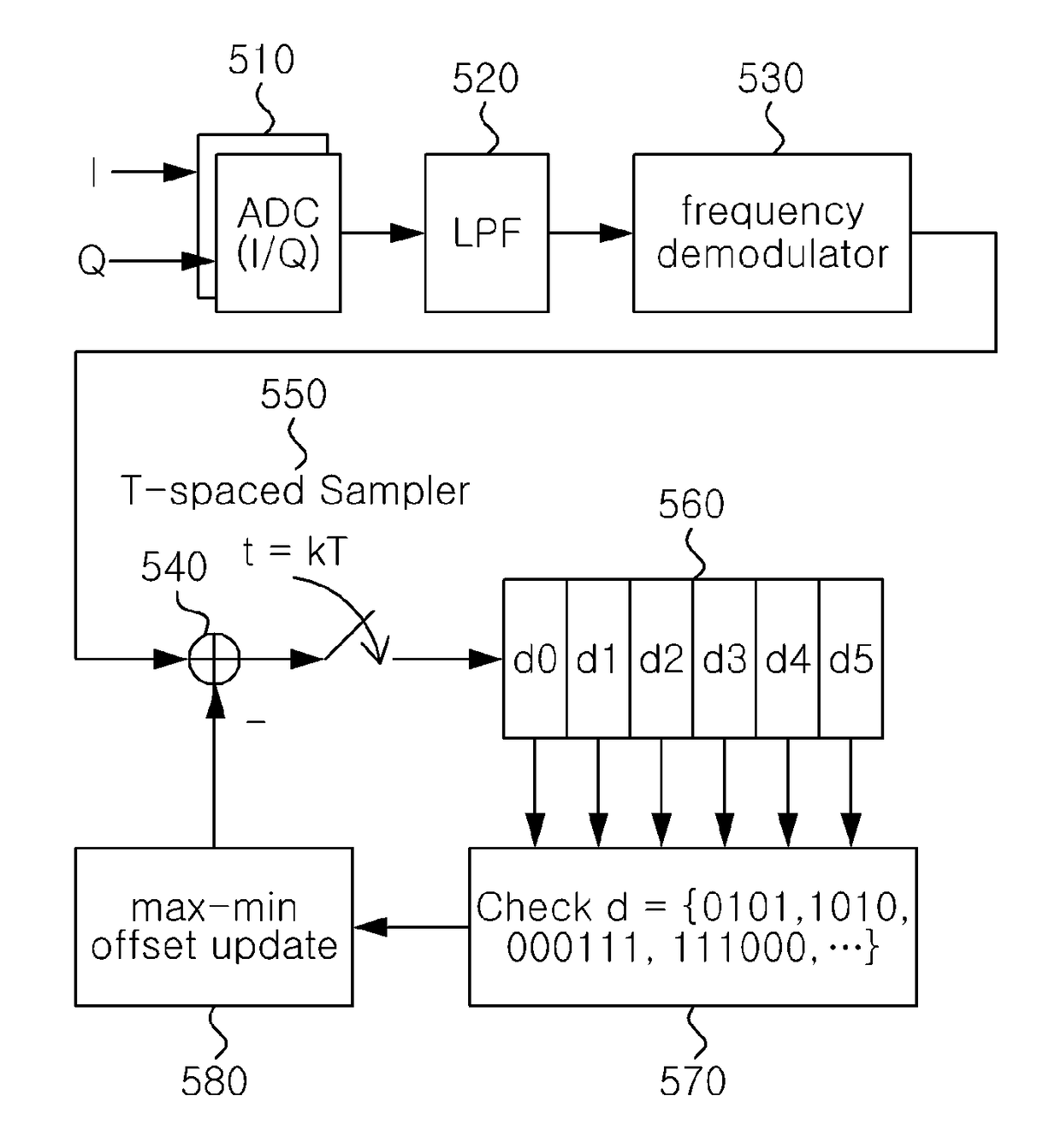
[0051]FIG. 4 is a diagram showing waveforms having passed through the frequency demodulator of a receiver and a “minimum-maximum average value” carrier offset estimation method.

[0052]When carrier offset occurs, a baseband frequency-demodulated waveform shows the state in which the average value of frequency shifts is not zero but has been biased by a constant value corresponding to the magnitude of the carrier offset. In this case, the constant value of the biased offset is i...


PUM


Abstract

Disclosed herein are a Bluetooth signal receiving device and method. The Bluetooth signal receiving device includes a frequency shift demodulator circuit, a sampler circuit, a training bit pattern discriminator circuit, and a frequency offset compensation circuit. The frequency shift demodulator circuit generates a baseband signal by performing frequency shift demodulation on a received signal, and generates a frequency proportion signal having a value proportional to the frequency of the baseband signal. The sampler circuit generates a plurality of series of bit streams from the frequency proportion signal. The training bit pattern discriminator circuit determines whether the plurality of series of bit streams generated by the sampler circuit satisfies a training bit pattern condition. The frequency offset compensation circuit compensates the frequency proportion signal by using a measured error metric as a effective error metric when the plurality of series of bit streams satisfies the training bit pattern condition.

Description

CROSS-REFERENCE TO RELATED APPLICATION[0001]This application claims under 35 U.S.C. § 119(a) the benefit of Korean Patent Application No. 10-2015-0189398 filed on Dec. 30, 2015, which is incorporated herein by reference.TECHNICAL FIELD[0002]The present invention relates to technology for a carrier frequency offset compensation method for a Bluetooth Smart receiving device, and more particularly to a method of compensating for the offset of a carrier frequency by applying a selective bit stream decision-oriented technique in a Bluetooth Smart device, and a circuit to which the method is applied.[0003]The present invention was derived from the research conducted as a part of the Industrial Core Technology Development Project sponsored by the Korean Ministry of Trade, Industry and Energy and the Korea Institute of Industrial Technology Evaluation and Planning [Project Management Number: 10052626; Project Name: Development of BLE (Bluetooth Low-Energy) v4.2 Supporting Communication Semi...

Claims


Application Information

Patent Timeline
Patent Type & Authority Patents(United States)
IPC IPC(8): H04L27/06H04L27/22H04L27/148H04W4/00H04W4/80
CPCH04L27/148H04W4/80H04L27/22H04L27/0014H04L27/144
Inventor CHU, SANG YOUNGMOON, KI TAEHONG, SUK KYUN
Owner ABOV SEMICON
Why Eureka
Try Eureka