FM modulator output control during turn on
a modulator and output control technology, applied in the field of fm modulators, can solve the problems of annoying and distracting sounds for most consumers, large amplitude popping sound, annoying whistles, etc., and achieve the effect of preventing unwanted sounds
- Summary
- Abstract
- Description
- Claims
- Application Information
AI Technical Summary
Benefits of technology
Problems solved by technology
Method used
Image
Examples
Embodiment Construction
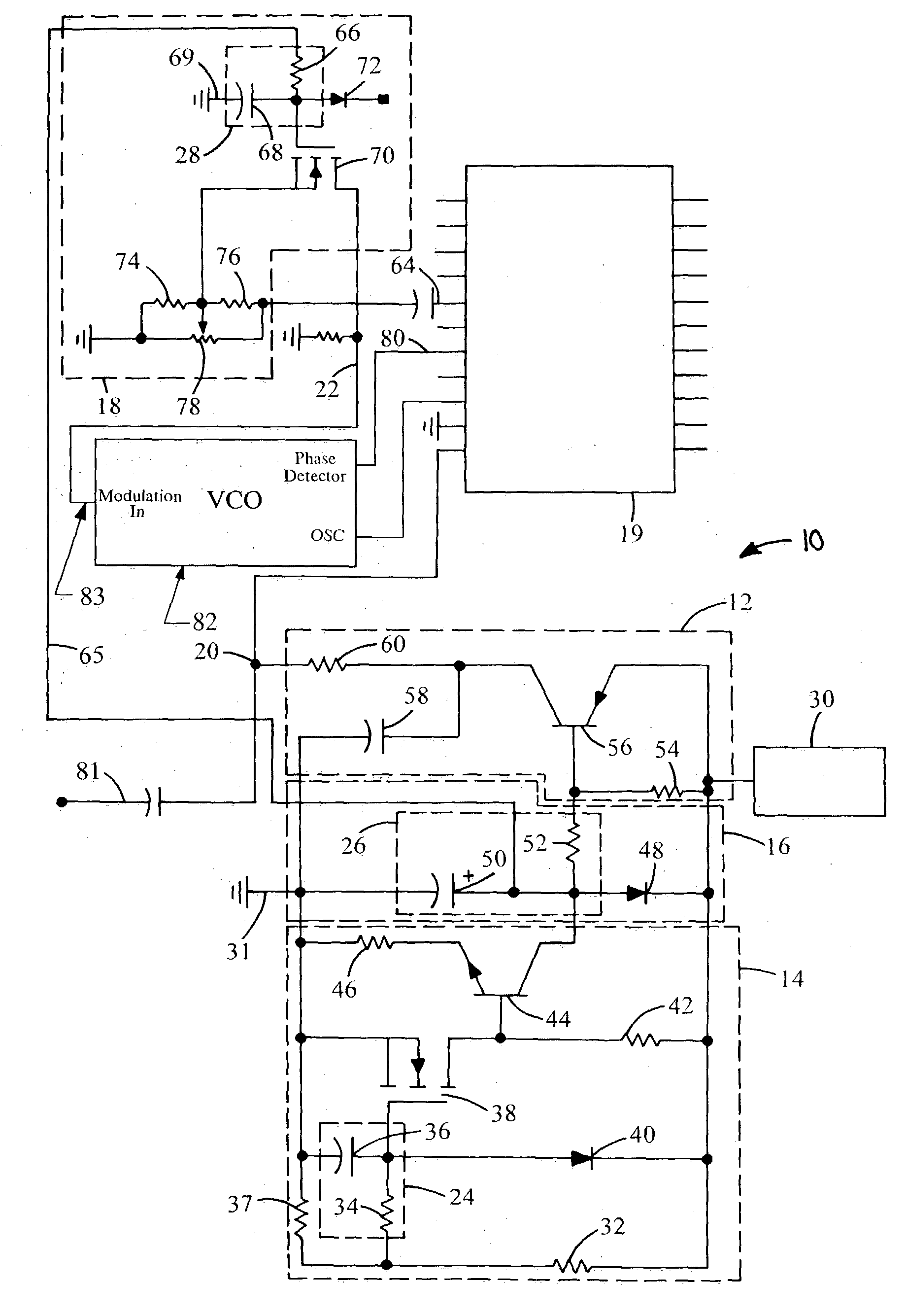
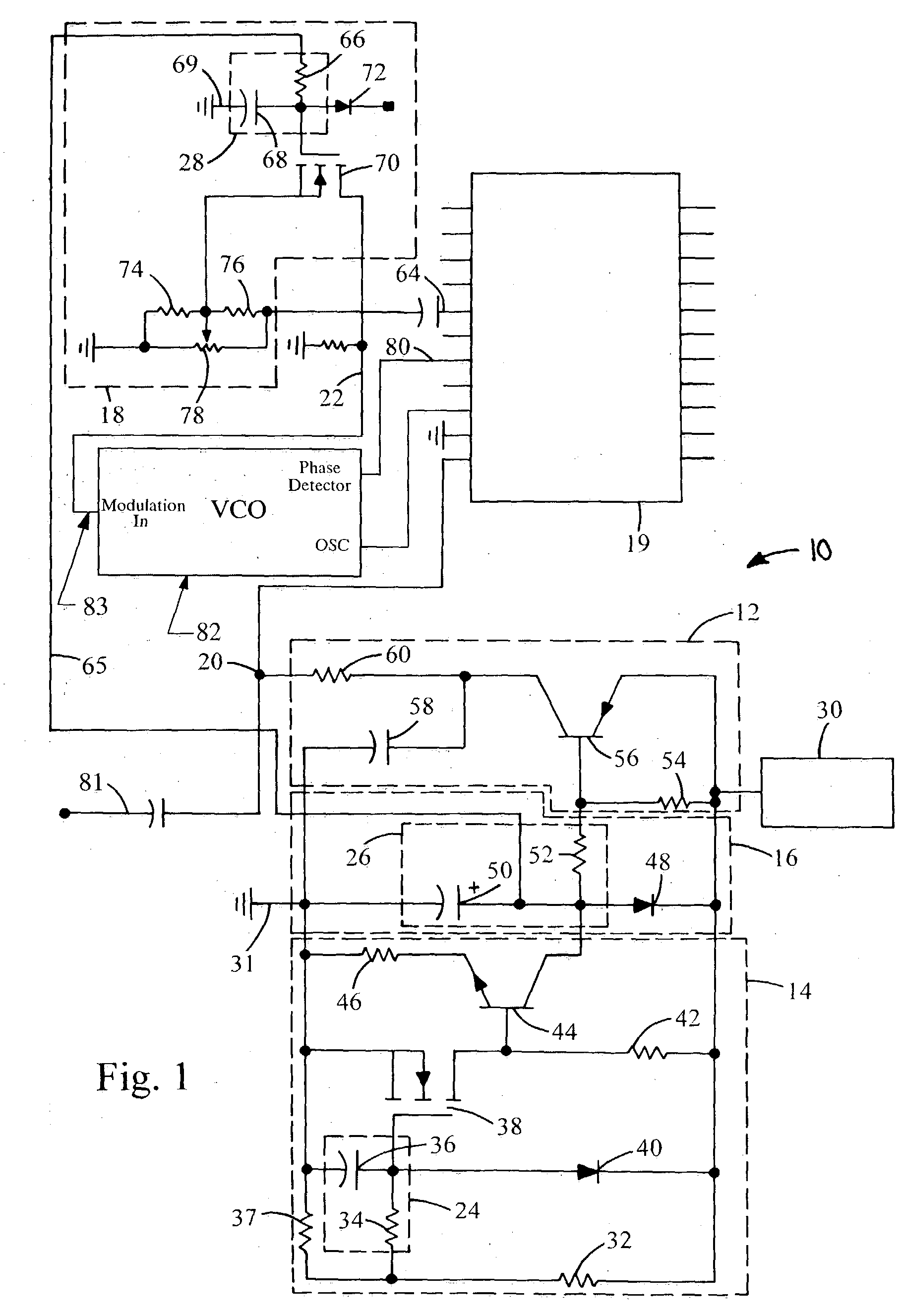
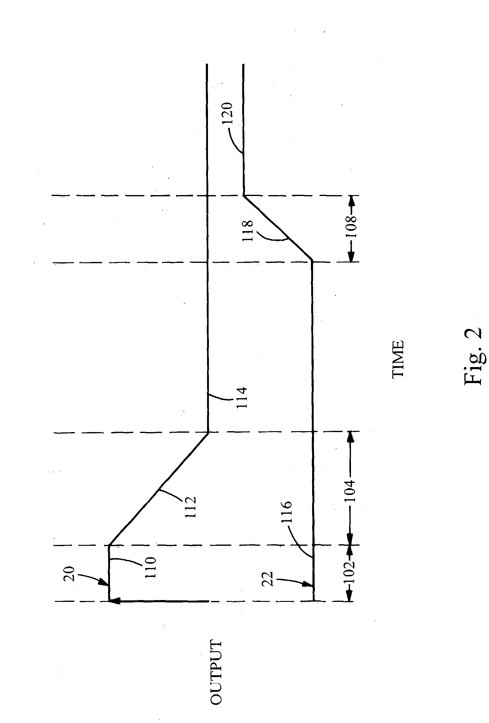
[0015] Now referring to FIGS. 1 and 2, a system embodying the principles of the present invention is illustrated therein and designated at 10. As its primary components, the system 10 includes a RF attenuator circuit 12, a delay switch 14, a RF ramp-up circuit 16, and an audio ramp-up circuit 18. As the FM modulator turns on, the voltage source 30 creates a positive voltage. The positive voltage immediately turns on the RF attenuator circuit 12, forcing the RF signal on lead 20, connected to the radio receiver input on 64, to minimum level, 30 dB below nominal level, 110.
[0016] Included in the attenuator circuit 12, resistor 54 is connected between the voltage source 30 and the base of the PNP transistor 56. The base of transistor 56 is connected through resistor 52 to capacitor 50. Capacitor 50 is initially discharged, and thus the base of PNP transistor 56 is held low. The low voltage on the base of PNP transistor 56 allows the transistor 56 to fully saturate, applying a positive...
PUM
 Abstract
Description
Claims
Application Information
 - R&D
- Intellectual Property
- Life Sciences
- Materials
- Tech Scout
- Unparalleled Data Quality
- Higher Quality Content
- 60% Fewer Hallucinations
Browse by: Latest US Patents, China's latest patents, Technical Efficacy Thesaurus, Application Domain, Technology Topic, Popular Technical Reports.
© 2025 PatSnap. All rights reserved.Legal|Privacy policy|Modern Slavery Act Transparency Statement|Sitemap|About US| Contact US: help@patsnap.com


