FM modulator output control during turn on

a modulator and output control technology, applied in the field of fm modulators, can solve the problems of annoying and distracting sounds for most consumers, large amplitude popping sound, annoying whistles, etc., and achieve the effect of preventing unwanted sounds

Inactive Publication Date: 2006-09-12
VISTEON GLOBAL TECH INC
View PDF17 Cites 1 Cited by
  • Summary
  • Abstract
  • Description
  • Claims
  • Application Information

AI Technical Summary

Benefits of technology

[0009]In satisfying the above need, as well as overcoming the enumerated drawbacks and other limitations of the related art, the present invention provides a system and a method to prevent undesired sounds during FM modulator turn on, including initial power up, frequency tuning, and audio output.
[0010]The system includes an RF attenuator circuit, a delay switch circuit, an RF ramp up circuit, and audio ramp up circuit. The RF attenuator circuit significantly reduces the RF signal from the FM modulator when the FM modulator is initially turned on. Attenuating the RF signal significantly reduces the whistle caused by the heterodyning of the RF signal of the FM modulator with the local oscillator contained in the vehicle radio receiver. Meanwhile, the PLL of the FM modulator is still able to precisely lock on to the selected radio frequency. Once the PLL if the FM modulator is locked onto the selected frequency, the heterodyning of the RF output of the FM modulator and the local oscillator of the vehicle radio receiver can no longer occur, thereby eliminating the possibility of a whistle. The time interval that the RF attenuator is activated is controlled by the delay switch circuit. After allowing time for the FM modulator PLL to lock onto the selected radio frequency signal, the time delay switch activates the RF ramp up circuit. The RF ramp up circuit gradually increases the FM modulator RF output signal level by gradually deactivating the RF attenuator circuit. The gradual increase of the RF level of the modulator output is intentionally slower than the response time of the vehicle radio receiver AGC system, thus allowing the radio vehicle AGC system to follow the RF signal level from the FM modulator RF output, thereby eliminating any popping sounds at the output of the vehicle radio receiver as the RF signal from the FM modulator is provided to the radio receiver.
[0011]As the time delay switch is activated a capacitor in the audio ramp up circuit is charged. As a result of the increasing voltage on this capacitor, the audio ramp up circuit gradually increases the stereo composite signal fed into the FM modulator input, thus eliminating sudden changes in the audio output of the vehicle radio receiver.

Problems solved by technology

These sounds are annoying and distracting to most consumers.
One undesired sound is an annoying whistle from high to low-frequency.
For example, if the RF level is switched on very quickly, the AGC of the receiver will not be able to track the input signal, therefore the end result will be a large amplitude popping sound.
Consumers perceive pops and whistles as being indicative of a poor quality radio, thereby making the sounds highly undesirable for manufacturers.

Method used


Image

  • FM modulator output control during turn on
  • FM modulator output control during turn on
  • FM modulator output control during turn on

Examples


Embodiment Construction

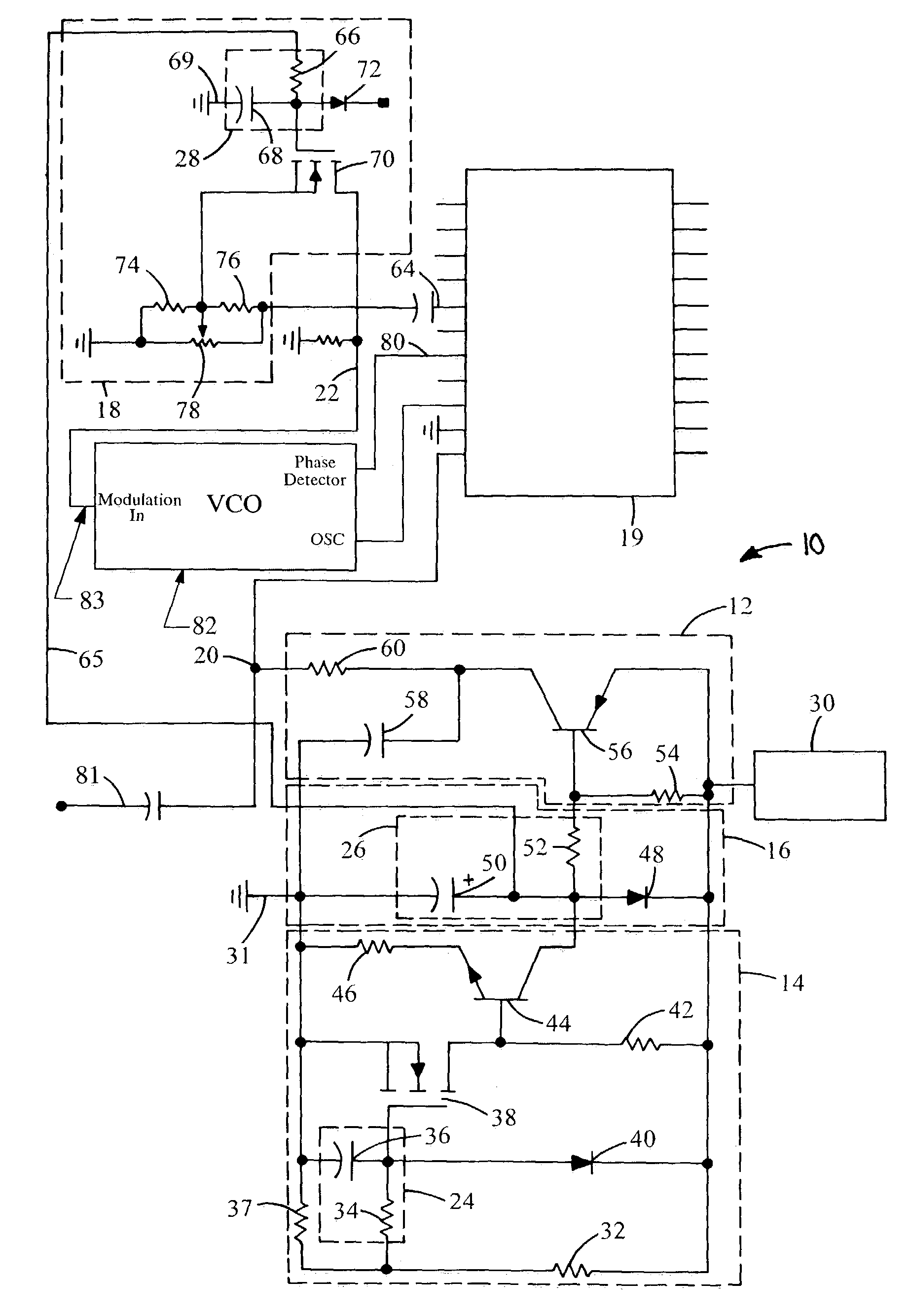
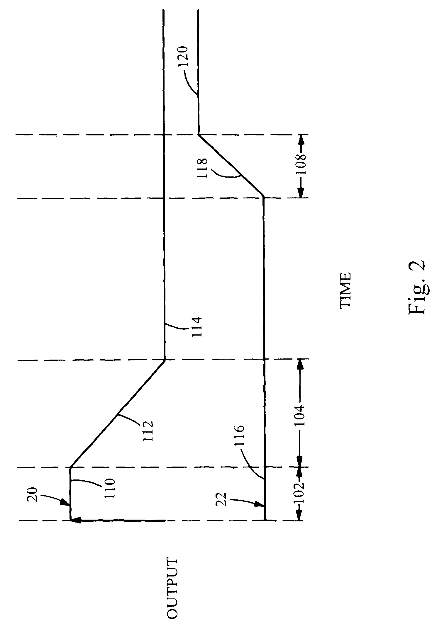
[0015]Now referring to FIGS. 1 and 2, a system embodying the principles of the present invention is illustrated therein and designated at 10. As its primary components, the system 10 includes a RF attenuator circuit 12, a delay switch 14, a RF ramp-up circuit 16, and an audio ramp-up circuit 18. As the FM modulator turns on, the voltage source 30 creates a positive voltage. The positive voltage immediately turns on the RF attenuator circuit 12, forcing the RF signal on lead 20, connected to the radio receiver input on 64, to minimum level, 30 dB below nominal level, 110.

[0016]Included in the attenuator circuit 12, resistor 54 is connected between the voltage source 30 and the base of the PNP transistor 56. The base of transistor 56 is connected through resistor 52 to capacitor 50. Capacitor 50 is initially discharged, and thus the base of PNP transistor 56 is held low. The low voltage on the base of PNP transistor 56 allows the transistor 56 to fully saturate, applying a positive vo...


PUM


Abstract

The present invention provides a system and a method to prevent undesired sounds during FM modulator turn on. The system includes an RF attenuator circuit, a delay switch circuit, an RF ramp up circuit, and audio ramp up circuit. The RF attenuator circuit significantly reduces the RF signal from the FM modulator when the FM modulator is initially turned on, which significantly reduce whistle caused by the RF signal from the modulator beating with the local oscillator in the radio receiver. After allowing time for the PLL to lock onto the RF signal, the time delay switch circuit becomes active and charges the RF ramp up circuit. The RF ramp up circuit gradually increases the RF signal by gradually deactivating the RF attenuator circuit. The gradual increase of the RF signal is slower than the response time of the radio AGC, thereby preventing any pop as the RF signal is provided to the radio receiver.

Description

BACKGROUND[0001]1. Field of the Invention[0002]The present invention generally relates to an FM modulator. More specifically, the invention relates to a system for reducing undesirable sounds associated with the FM modulator turn on.[0003]2. Description of Related Art[0004]One application of an FM modulator includes modulating stereophonic composite audio signals from peripheral devices such as, DVD players, allowing the resulting RF signal to be played by a standard stereo radio receiver. The ability to use peripheral devices with a standard radio receiver can provide a significant cost savings for automotive applications. However, it is recognized that a certain set of chirps and pops are created in association with FM modulator turn on. These sounds are annoying and distracting to most consumers.[0005]One undesired sound is an annoying whistle from high to low-frequency. FM modulators employ a phase lock loop (PLL) which facilitates selection and precise control of frequency of t...

Claims


Application Information

Patent Timeline
Patent Type & Authority Patents(United States)
IPC IPC(8): H04B1/10H03C3/00H03C3/02H04B1/04H04B1/16H04B1/38
CPCH04B1/0475H03C3/02
Inventor KENNEDY, JOHN F.TILLO, EDMUND J.
Owner VISTEON GLOBAL TECH INC
Why Eureka
Try Eureka