Band clip

a technology of band clip and sleeve, which is applied in the direction of screws, threaded fasteners, transportation and packaging, etc., can solve the problems of increasing the dimension of the attachment target, such as the panel, to the electrical wire, and the risk of error in the routing path of the electrical wire in the vehicle, so as to suppress the dimension, suppress interference, and be easily positioned

Inactive Publication Date: 2018-03-13
SUMITOMO WIRING SYST LTD
View PDF17 Cites 3 Cited by
  • Summary
  • Abstract
  • Description
  • Claims
  • Application Information

AI Technical Summary

Benefits of technology

[0007]In view of this, an object of the present design is to provide a technique that, when an electrical wire has been attached to an attachment target by a clip, makes it possible to position a shaft portion of the clip toward the widthwise center of the electrical wire while also reducing the dimension from the attachment target to the electrical wire.
[0011]According to the band clip of the first to third aspects, the band locking portion is provided in the shaft portion, thus making it possible to suppress the dimension from the attachment target to the electrical wire when the electrical wire is attached to the attachment target using the band clip. Also, the band main body portion is formed so as to extend in the direction orthogonal to the extending direction of the shaft portion, and the hinge portion includes the curved portion that is formed with a curved shape so as to extend from the direction orthogonal to the extending direction of the shaft portion toward the side opposite to the side toward which the shaft portion extends, and therefore by bending the entirety of the curved portion a large amount, the base portion of the band main body portion can be positioned toward the center of the shaft portion. Accordingly, the shaft portion of the band clip can be positioned toward the widthwise center of the electrical wire.
[0012]In particular, according to the band clip of the second aspect, the curved portion is formed such that the cross-sectional area thereof is smallest in the lengthwise intermediate portion thereof, thus making it likely for the entirety of the curved portion to bend, while bending a larger amount in the portion with the smallest cross-sectional area. Accordingly, the shaft portion of the band clip is more easily positioned toward the widthwise center of the electrical wire.
[0013]In particular, according to the clip of the third aspect, the receding portion is formed in the body portion such that the outer edge of the body portion recedes toward the bottom portion, the receding portion having a width greater than or equal to the width of the hinge portion, and the hinge portion extends outward through the portion in which the receding portion is formed in a view from the extending direction of the shaft portion, and therefore it is possible to suppress interference between the hinge portion and the dish portion, even in the case where the hinge portion bends a large amount.

Problems solved by technology

Incidentally, when a belt (band) and a buckle (band fixing portion) are provided on the bottom of a stabilizer, as with the band clip described in Patent Document 1, there is a risk of an increase in the dimension from the attachment target, such as a panel, to electrical wires.
In this case, there is a risk of error in the routing path of the electrical wires in the vehicle.

Method used


Image

  • Band clip
  • Band clip
  • Band clip

Examples


Embodiment Construction

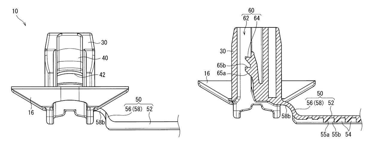
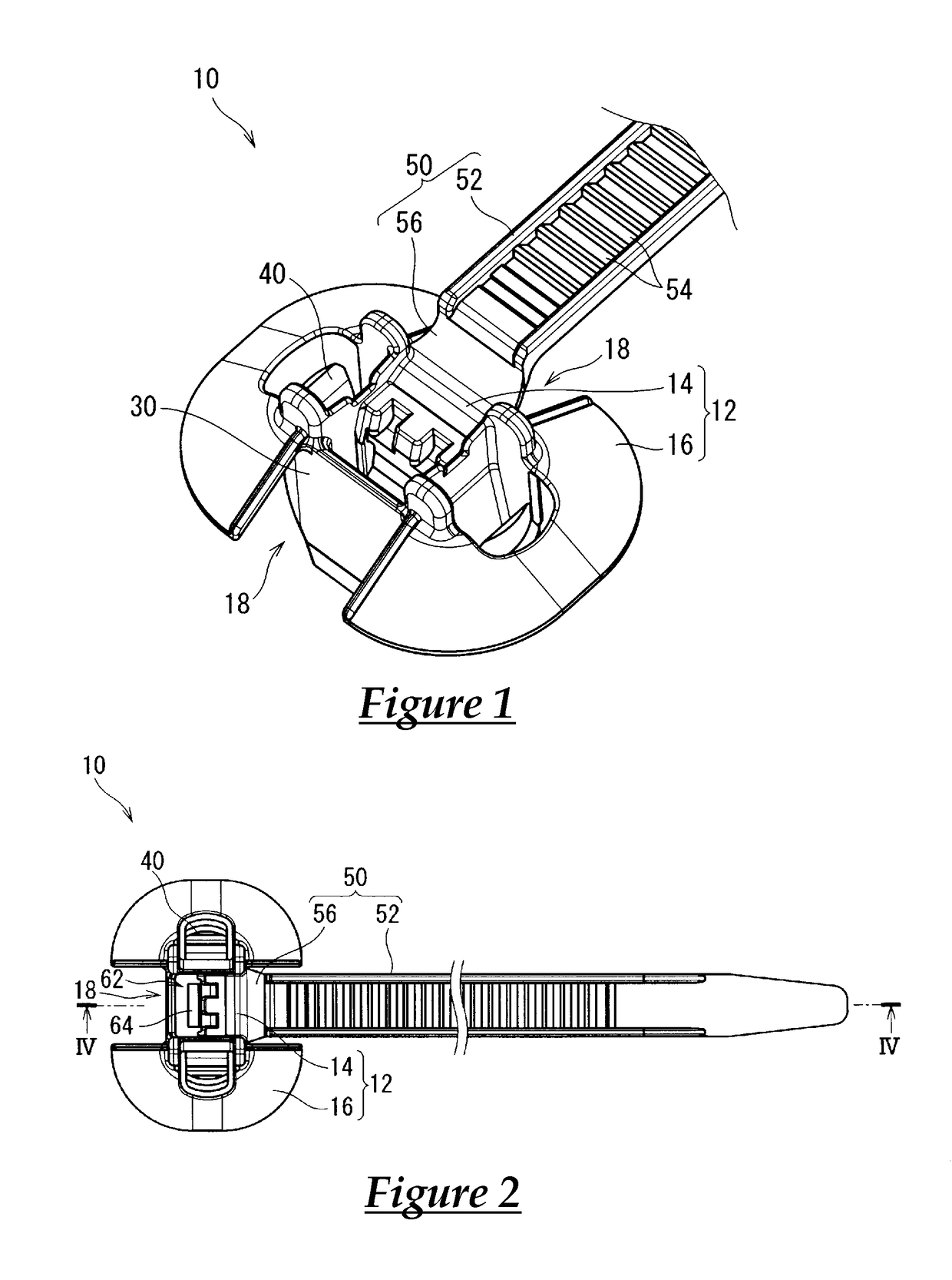
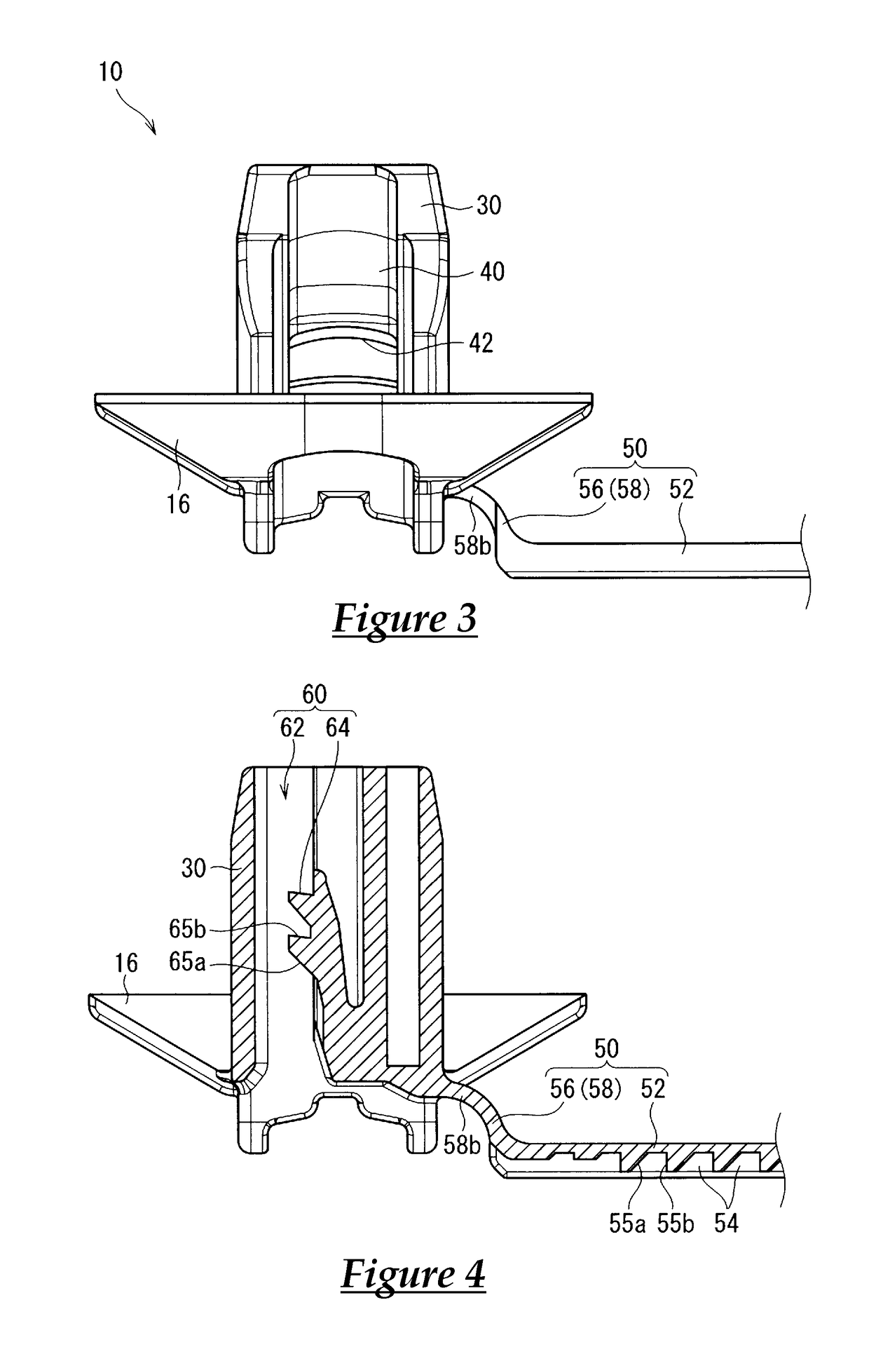
[0025]Hereinafter, a band clip 10 according to an embodiment will be described. FIG. 1 is a perspective view of the band clip 10 according to the embodiment. FIG. 2 is a plan view of the band clip 10 according to the embodiment. FIG. 3 is a front view of the band clip 10 according to the embodiment. FIG. 4 is a cross-sectional view taken along line IV-IV in FIG. 2.

[0026]The band clip 10 according to the embodiment is a member by which another member routed in a vehicle, such as an electrical wire, is fixed to the vehicle. The band clip 10 according to the embodiment includes a dish portion 12, a shaft portion 30, locking portions 40, a band portion 50, and a band locking portion 60. The band clip 10 is formed so as to be able to be inserted into an attachment hole formed in an attachment target, such as a vehicle body panel, and so as to be able to be locked after insertion.

[0027]The dish portion 12 includes a bottom portion 14 and a body portion 16, and is formed in a dish shape. T...


PUM


Abstract

A Band clip that, when an electrical wire has been attached to a target by the clip, makes it possible to position a shaft portion of the clip toward the widthwise center of the electrical wire while also reducing the dimension from the target to the electrical wire. The band clip includes a dish portion, a shaft portion, a locking portion, a band portion, and a band locking portion. The band portion includes a hinge portion, one end of which is connected to the dish portion, and a band main body portion formed with a narrow belt shape so as to extend from the other end of the hinge portion. The band main body portion is formed so as to extend in a direction orthogonal to the extending direction of the shaft portion, and the hinge portion includes a curved portion.

Description

CROSS REFERENCE TO RELATED APPLICATIONS[0001]This application claims the priority of Japanese patent application JP2014-204652 filed on Oct. 3, 2014, the entire contents of which are incorporated herein.TECHNICAL FIELD[0002]This invention relates to a band clip for fixing electrical wires or the like to a vehicle body.BACKGROUND ART[0003]A band clip (also called a band clamp) for fixing electrical wires or the like to a vehicle is disclosed in Patent Document 1, for example.[0004]The band clip described in Patent Document 1 (JP2002-174210A) includes a dish-shaped stabilizer (dish portion), and slits cut out from an open portion of the stabilizer increase the amount of flexure while also ensuring elastic reaction force, thus suppressing looseness of the clip.SUMMARY OF INVENTION[0005]Incidentally, when a belt (band) and a buckle (band fixing portion) are provided on the bottom of a stabilizer, as with the band clip described in Patent Document 1, there is a risk of an increase in the...

Claims


Application Information

Patent Timeline
Patent Type & Authority Patents(United States)
IPC IPC(8): F16L3/00B60R16/02H02G3/22F16B2/08F16B19/00F16L3/137
CPCB60R16/0215F16B2/08H02G3/22F16L3/137F16B19/00H02G3/32F16B5/0685B65D63/1072
Inventor NAKAGAWA, KAZUKINAGAYASU, DAIKI
Owner SUMITOMO WIRING SYST LTD
Why Eureka
Try Eureka