Goal recognition system and method for recognizing a goal

a goal recognition and goal technology, applied in the field of goal recognition systems and methods for recognizing goals, can solve the problems of inability to ensure the reliability of signal transmission and inability to detect with the greatest reliability, and achieve the effect of high reliability

Active Publication Date: 2018-03-20
PIXARGUS
View PDF16 Cites 5 Cited by
  • Summary
  • Abstract
  • Description
  • Claims
  • Application Information

AI Technical Summary

Benefits of technology

[0009]It is therefore an object of the invention to overcome the above disadvantages and to create a technology for recognizing a goal, such that it will ensure a high reliability using simple and inexpensive means.
[0015]Another embodiment of the invention, provides for a goal recognition system in which multiple cameras monitor a goal line plane spanned by a crossbar of a goal. A mirror module, which aligns the beam path of the camera along the goal line plane, is assigned to at least one of these cameras. This has the advantage that the camera with its lens system may not be aligned precisely in the direction of the goal line plane but instead, thanks to the mirror module, it can also be disposed in a different position. This is advantageous in particular when the camera is mounted at least partially or completely in a part of the framework, i.e., inside a post or inside the crossbar of the goal. In this case, the camera may be aligned with its longitudinal axis essentially parallel to the longitudinal axis of the post or crossbar, which permits a particular space-saving accommodation.
[0016]In the same way as the cameras for monitoring the goal line plane, at least one camera module may also be accommodated at least partially or completely inside a part of the framework of a goal, i.e., inside a post or a crossbar. As an alternative to this, it is also possible for the camera module to be positioned outside of the framework, e.g., on its own stand or the like. In this way, the camera module may be positioned at the level of the goal end line, or as an alternative, also on at least one side edge of the playing field. Such an arrangement of the camera module also ensures that it can reliably monitor the aforementioned sectors outside of the goal.
[0018]In the same way as with the cameras for monitoring the goal line plane, it may be advantageous with regard to the camera module if a mirror module which aligned the beam path of a camera of the camera module in the sector outside of the goal is assigned to the camera module. Due to the combination with a mirror module, there are greater degrees of freedom for the positioning of the camera module with respect to the framework of the goal. In mounting the camera module at least partially inside a part of the framework, for example, inside a post or a crossbar, thanks to the combination with the mirror module, it is possible to arrange the camera module in such a way that the longitudinal axis of a camera of the camera module is arranged essentially parallel to the longitudinal axis of a post or of a crossbar of the framework. This results in a compact design.
[0019]According to an embodiment, assembly of the cameras in or on the framework of the goal can be facilitated by the fact that the mirror module together with one camera for monitoring the goal line plane and / or together with the camera module form(s) a structural unit which may also include suitable fastening elements or the like. This permits free assembly of the structural unit, which can then be assembled in a single additional manufacturing step in a time-saving manner or in the framework of the goal.
[0022]According to an embodiment, the mirror module may have a main mirror which aligns the beam path of a camera assigned to it along the goal line plane and / or in the sector outside of the goal. The variability of the arrangement of the camera and / or the camera module with respect to the most space-saving arrangement, for example, inside the framework can be further improved by means of an additional mirror which is provided between the main mirror and the respective assigned camera.

Problems solved by technology

The disadvantage here is that it is impossible to detect with the greatest reliability when the ball has completely crossed through a goal line plane because in the usual rules of play a goal is to be counted only in this case.
One disadvantage here is the configuration of the transmitter inside the ball because reliable transmission of signals cannot be ensured at all times due to vibrations or the like.

Method used


Image

  • Goal recognition system and method for recognizing a goal
  • Goal recognition system and method for recognizing a goal
  • Goal recognition system and method for recognizing a goal

Examples


Embodiment Construction

[0034]This invention is particularly suitable for those types of sports in which a playing body is played in the direction of an opponent's goal which spans a goal line plane. Examples of such types of sports include in particular soccer, handball, ice hockey, rugby, American football, field hockey or even polo. The following description of one embodiment of the invention relates to the field of soccer sports, where the playing body is referred to as a ball accordingly but it should be pointed out that the reference to the field of soccer sports is not to be taken as a restriction on the invention.

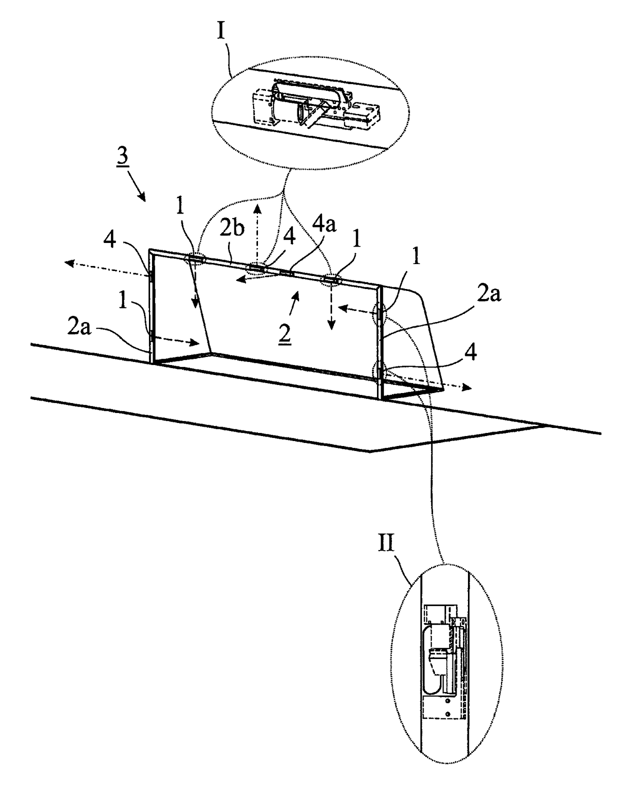
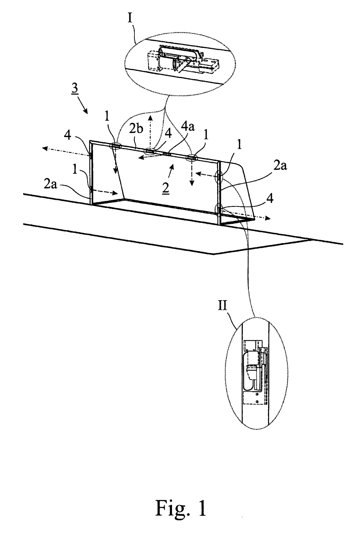
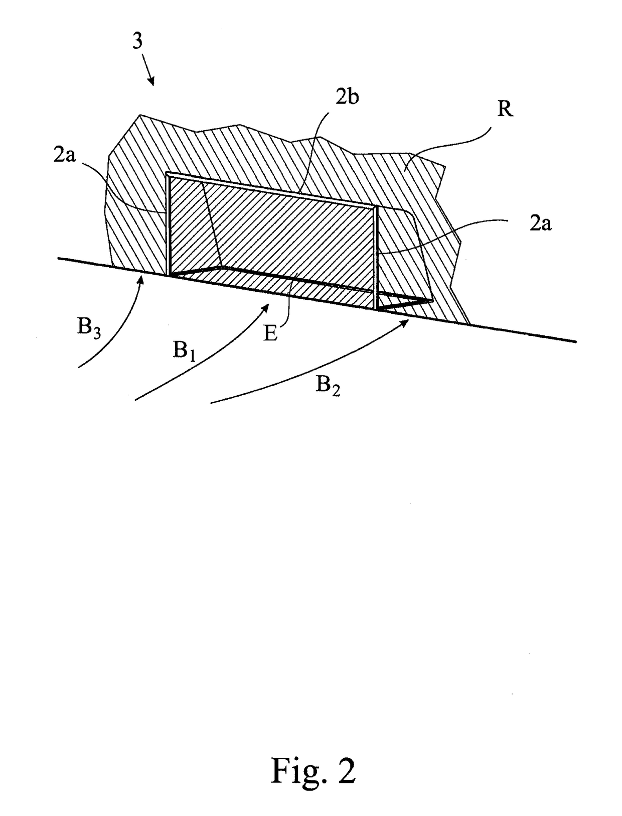
[0035]To illustrate the goal recognition system according to the invention, FIG. 1 shows a simplified perspective view of a goal on which several cameras are provided. Specifically, multiple cameras 1 are mounted on a framework 2 of a goal 3, such that both inside a post 2a and also inside a crossbar 2b. The cameras 1 serve to monitor a goal line plane E (cf. FIG. 2) where the main axis of...


PUM


Abstract

A system and a method for goal recognition, in which a plurality of cameras monitor a goal line plane that is generated by a framework for a goal, wherein at least one camera module is provided which can be used to monitor a sector outside the goal laterally adjacent to the framework or in front of the framework in the direction of a playing field in order to determine a trajectory for a playing body in the region of the playing field in the direction of the goal, wherein the operation of the cameras for monitoring the goal line plane and / or the evaluation of the image data therefrom can be controlled on the basis of the image data from the camera module.

Description

[0001]This nonprovisional application is a continuation of International Application No. PCT / DE2012 / 001161, which was filed on Dec. 5, 2012, and which claims priority to German Patent Application No. 10 2011 120 368.4, which was filed in Germany on Dec. 7, 2011, and which are both herein incorporated by reference.BACKGROUND OF THE INVENTION[0002]Field of the Invention[0003]The present invention relates to a goal recognition system and a method for recognizing a goal.[0004]Description of the Background Art[0005]In many types of sports in which a moving play object is played in the direction of a goal or the like, there is a need for determining with a high reliability whether or not the play object has past the goal. Examples of such types of sports include soccer, handball or ice hockey. Traditionally various technical aids have been known, for example, the use of sensors and / or cameras to determine whether the play object has crossed a goal line or the like. A few known technologie...

Claims


Application Information

Patent Timeline
Patent Type & Authority Patents(United States)
IPC IPC(8): G06T7/00A63B71/06G06T7/70H04N5/247A63B63/00A63B24/00
CPCH04N5/247A63B63/004A63B71/0605G06T7/70A63B2024/0028G06T2207/30241A63B2220/807A63B2225/12G06T2207/10004G06T2207/10016G06T2207/30224A63B2220/806H04N23/90
Inventor LINDNER, BJOERNPHILIPPS, JUERGENBEAUJEAN, RENE
Owner PIXARGUS
Why Eureka
Try Eureka