Cryogenic cooling apparatus and system

a cooling apparatus and cryogenic technology, applied in the field of cryogenic cooling apparatus, can solve the problems of increasing the amount of physical materials present and placing additional requirements on the cooling system, and achieve the effects of compact geometrical arrangement, reduced axial length, and compact arrangemen

Active Publication Date: 2018-03-27
OXFORD INSTR NANOTECH TOOLS
View PDF9 Cites 1 Cited by
  • Summary
  • Abstract
  • Description
  • Claims
  • Application Information

AI Technical Summary

Benefits of technology

[0011]The use of conductive cooling of the primary (experimental) and demagnetisation magnets, together with each of their respective shielding magnets, represents a radical departure from known practices. The conductively cooled shielding magnets of the present invention have an entirely different design when compared with known demagnetisation systems. In particular, these now take a cylindrical form whereby the geometrical envelope of the shielding magnet coil encloses the magnet which is shielded. Thus the geometry of the shielding magnet may be thought as a right circular cylinder with open ends and the respective magnet which it shields is preferably positioned centrally within the cylinder and has an axial dimension which is less than that of the shielding magnet. This geometry is in complete contrast with previous demagnetisation system magnetic shields. Furthermore, it will be noted that typically only a single coil shielding magnet is provided rather than the use of multiple coils. The geometric centre of the coil of the shielding magnet therefore typically coincides with that of the respective magnet which it shields. This new design therefore largely removes the need for mechanical force constraint of the shielding coils which was required in prior systems to withstand axial forces of the order of thousands of Newtons due to the multiplicity and off-centre positions of the shielding coils.
[0012]The removal of the use of liquid cryogens also removes the constraint on the radius of the shielding coils, although an increased radius does increase the amount of physical material present and therefore places additional requirements on the cooling system.
[0016]As will be understood, the specific design of the shielding coil of the shielding magnet in each case is dependent upon the geometry of the magnetic shield as well as any other dimensional requirements of the specific system in question. Preferably however, one or each of the primary shielding magnet and the demagnetisation shielding magnet have an axial length which is greater than the dimension of the respective magnet that they shield by between 10 and 40%. The minimum diameter of the shielding magnet coil in each case will of course be greater than the maximum diameter of the coils of the magnet which it shields. Thus the containment of either the primary or demagnetisation magnet within its respective shielding magnet is assured by the larger axial and radial dimensions of the shielding magnet.
[0019]Since the respective magnets are conductively cooled, there is no need for the provision of liquid cryogen to provide the cooling effect. Typically one or more vacuum chambers are provided within which the primary, primary shielding, demagnetisation and demagnetisation shielding magnets are contained, such that, when in use, the said magnets are each located within a vacuum environment. This environment is therefore absent any liquid cryogen. It is also contemplated that a flow cooling approach could be adopted to cool the magnets in which a cryogen such as gaseous helium is flowed through ducts in thermal communication with the magnet windings. This approach may be particularly beneficial for use with magnets formed from high temperature superconductors.
[0021]As will be understood, a metallic material such as high purity copper may be used to provide the thermally conductive members of the conductive cooling assembly, these members coupling with the refrigeration system. Likewise, high purity copper may also be used to thermally connect the demagnetisation material and a sample stage of the target region. A particularly beneficial class of material for use as the demagnetisation material is those based on PrNi5 which exhibit excellent demagnetisation cooling performance. Such materials may also be used as the thermally conductive members.
[0023]The use of conductive cooling in association with the cylindrical shielding magnet design allows for a more compact arrangement of the magnets in comparison with known systems, due to the axial extent of the shielding magnet coils in particular being less distant from the magnet centre. This in turn allows the use of a cryostat having a reduced axial length. Any cryocooler, dilution refrigerator or equivalent apparatus providing the refrigeration may be arranged on axes which are orthogonal to the axis defining the magnets so as to provide for a more compact geometrical arrangement.

Problems solved by technology

The removal of the use of liquid cryogens also removes the constraint on the radius of the shielding coils, although an increased radius does increase the amount of physical material present and therefore places additional requirements on the cooling system.

Method used


Image

  • Cryogenic cooling apparatus and system
  • Cryogenic cooling apparatus and system
  • Cryogenic cooling apparatus and system

Examples


Embodiment Construction

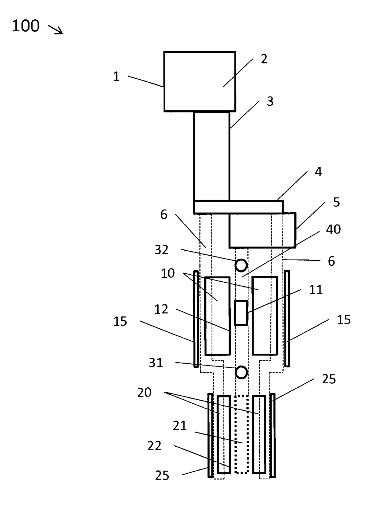
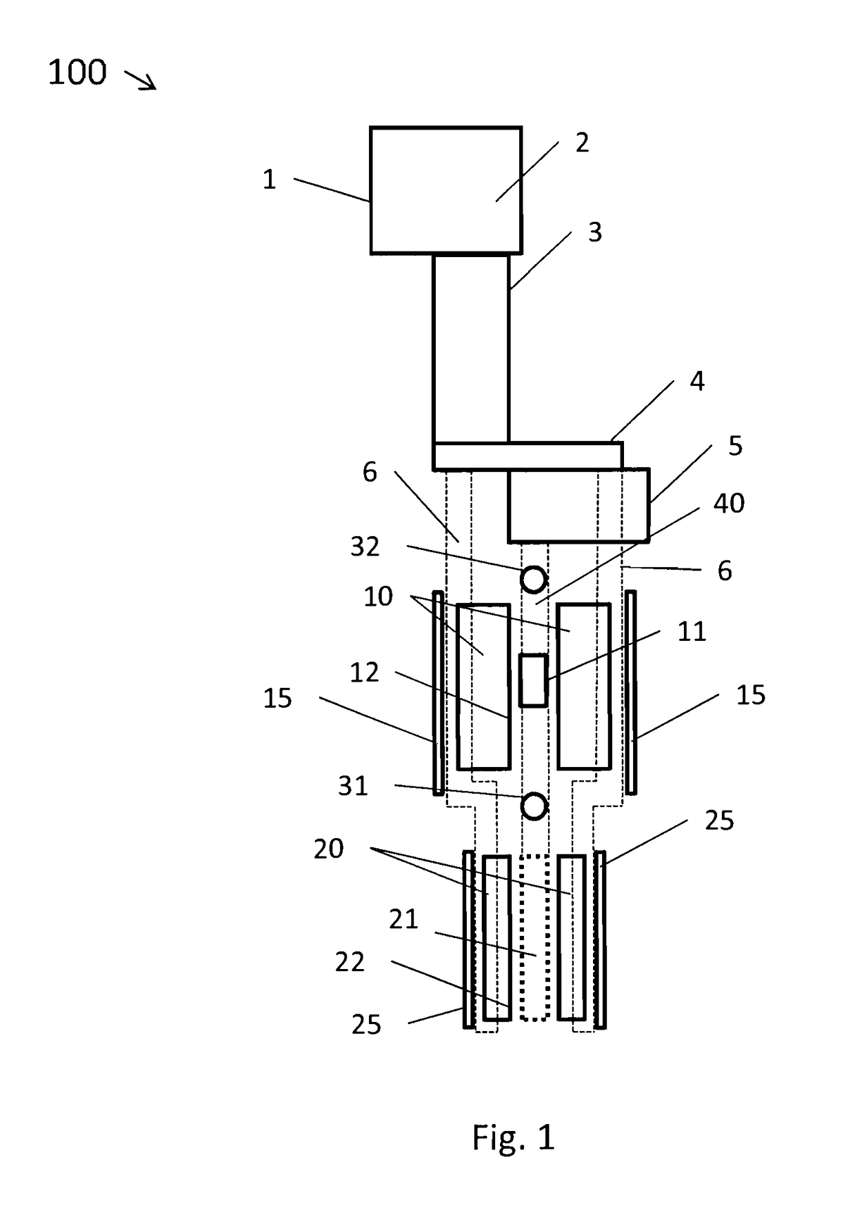
[0027]FIG. 1 shows an example demagnetisation cooling system generally illustrated at 100. The cooling power to the system is provided by a pulse tube refrigerator (PTR) 1 which in the present case is a two stage device. This has a cooling head 2 from which extend pulse and regenerator tubes generally illustrated at 3. Although this is a two stage device, only the second, lower temperature stage 4 is illustrated for simplicity. The tubes 3 and second stage 4, together with the further apparatus to be described below, are all contained in a vacuum cryostat which is not illustrated in FIG. 1 for clarity purposes. Particularly the PTR 1 is capable of providing a cooling power of around 1 Watt at a temperature of 4.2 Kelvin at the second stage 4. This cooling power is used within the present system in two ways. Firstly, the second stage 4 is used to provide cooling power for a dilution refrigerator shown schematically at 5. Secondly, the cooling power of the second stage 4 is used to co...


PUM

PropertyMeasurementUnit
temperatureaaaaaaaaaa

Abstract

Cryogenic cooling apparatus is disclosed for cooling a target region using the demagnetization cooling effect. The apparatus has a primary magnet for providing a magnetic field within the target region and a demagnetization magnet arranged to selectively provide conductive cooling to the target region. A primary shielding magnet substantially cancels the magnetic field from the primary magnet at least at a first position between the primary and demagnetization magnets. A demagnetization shielding magnet substantially cancels the magnetic field from the demagnetization magnet at least at the first position between the primary and demagnetization magnets. Each of the primary shielding magnet and demagnetization shielding magnet comprises a cylindrical superconducting coil having a geometric envelope which encloses the primary magnet and demagnetization magnet respectively. A conductive cooling assembly provides conductive cooling to each of the magnets. A cryogenic system including a cryostat, the apparatus and a refrigeration system is also provided.

Description

FIELD OF THE INVENTION[0001]The present invention relates to a cryogenic cooling apparatus which uses the entropic effect of demagnetisation to provide the cooling of a target region. The invention also relates to a refrigeration system including such cryogenic cooling apparatus.BACKGROUND TO THE INVENTION[0002]There is significant interest, both in scientific research and in certain commercial sectors, in being able to provide ultra-low temperature environments. Such environments can be thought of as having a temperature of 1 milliKelvin or less. This temperature range is beyond the reach of conventional dilution refrigerators. It is however possible to achieve such temperatures by using the effect of “nuclear demagnetisation”. Essentially, using this technique, a cooled member is located within a relatively strong magnetic field so as to align the nuclear spins, whilst at the same time also being cooled to a temperature of a few milliKelvin using a dilution refrigerator for exampl...

Claims


Application Information

Patent Timeline
Patent Type & Authority Patents(United States)
IPC IPC(8): F25B9/00F17C3/08F25B21/00H01F1/00F25D3/10F25B9/14F25D19/00H01F6/00
CPCF25B21/00F17C3/085F25B9/145F25D3/10F25D19/006Y02B30/66F25B2321/002F25B2321/0021H01F6/00Y02B30/00
Inventor KING, CHRIS
Owner OXFORD INSTR NANOTECH TOOLS
Why Eureka
Try Eureka