Battery assembly

a battery and assembly technology, applied in the field of battery assembly, can solve the problems of excessive installation space and significant increase in thickness of battery assembly, and achieve the effect of reducing the number of components to be assembled in assembling the battery assembly, efficient cooling structure and reducing volume efficiency

Active Publication Date: 2018-03-27
GS YUASA INT LTD
View PDF72 Cites 2 Cited by
  • Summary
  • Abstract
  • Description
  • Claims
  • Application Information

AI Technical Summary

Benefits of technology

[0022]In a battery assembly according to the present invention, insulating plates such as resin plates, for example, are integrally fixed to inner sides of metal plates of end plates; therefore, no resin battery holder has to be placed between the end plates and batteries at ends of a laminated battery body in order to provide insulation therebetween, and the number of components to be assembled in assembling the battery assembly is reduced.
[0023]In addition, since the insulating plates are integrally fixed to high-strength metal plates, plates each having a thickness smaller than that of a conventional battery holder are sufficiently used for the insulating plates, thus preventing the possibility that the volume efficiency of the battery assembly will be reduced by excessive thicknesses as in the case where the end plates are entirely made of resin.
[0024]Further, since the insulating plates are integrally fixed to the metal plates, the insulating plates are less likely to be distorted as another body by application of load thereto. Note that in the battery holders incorporated into the battery assembly, gaps are formed in advance in consideration of component tolerance. Due to the influence of the gaps, insulating parts of the end plates are distorted when the batteries are pressed and clamped between a pair of the end plates, and this distortion becomes pronounced when a plurality of the batteries are arranged in a row; however, in the present invention, occurrence of such distortion will be avoided. Such a phenomenon was found for the first time in the course of development of the present invention. Note that the gaps formed in consideration of component tolerance serve to smoothly carry out the step of fitting the batteries into the battery holders, and are created by making spacing between after-mentioned holding portions slightly longer than spacing between the batteries.
[0025]In the battery assembly according to the present invention, protrusions are formed at surfaces of the insulating plates, and tip portions of the protrusions are brought into contact with the batteries at the ends, thereby forming cooling passages; then, the cooling passages through which fluid is efficiently circulated are formed by spaces provided by abutment of the tip portions of the protrusions against the batteries. Note that cooling passages may also be formed by the battery holders in a similar manner. Such a structure is capable of implementing an efficient cooling structure while maintaining strength that withstands the clamed fixation. Note that as the shapes of the protrusions, ridged shapes or island shapes may be used.
[0026]In the battery assembly according to the present invention, a battery state detector for detecting a state of the battery at the end is attached to at least one of the pair of end plates; then, since the insulating plates such as resin plates, for example, are integrally fixed to the inner sides of the metal plates of the end plates, the resin plates and the metal plates are hardly distorted when the batteries are pressed and clamped, and the state of the battery may be detected with high accuracy for a long period of time.
[0027]Note that when the battery state detector is directly affixed to a surface of a battery case by using an adhesive, there occurs a problem that durability of the state detector is affected by swelling of the battery. This is a phenomenon that occurs when an adhesive layer cannot follow deformation of the surface of the battery case. The occurrence of this phenomenon becomes more pronounced as the deformation amount of the surface of the battery case is increased. Accordingly, when the battery state detector is attached to a lateral surface of the rectangular box type metal battery case, having the largest area, the deformation amount of this region will be greater than that of the other lateral surface; therefore, the durability is considerably reduced, thus making it difficult to detect the state with high accuracy.

Problems solved by technology

For example, in Patent Document 2, since end plates made of resin are used as illustrated in FIGS. 1 to 4, the thicknesses thereof are significantly increased, and the resulting battery assembly will occupy an excessive installation space.

Method used


Image

  • Battery assembly
  • Battery assembly
  • Battery assembly

Examples


Embodiment Construction

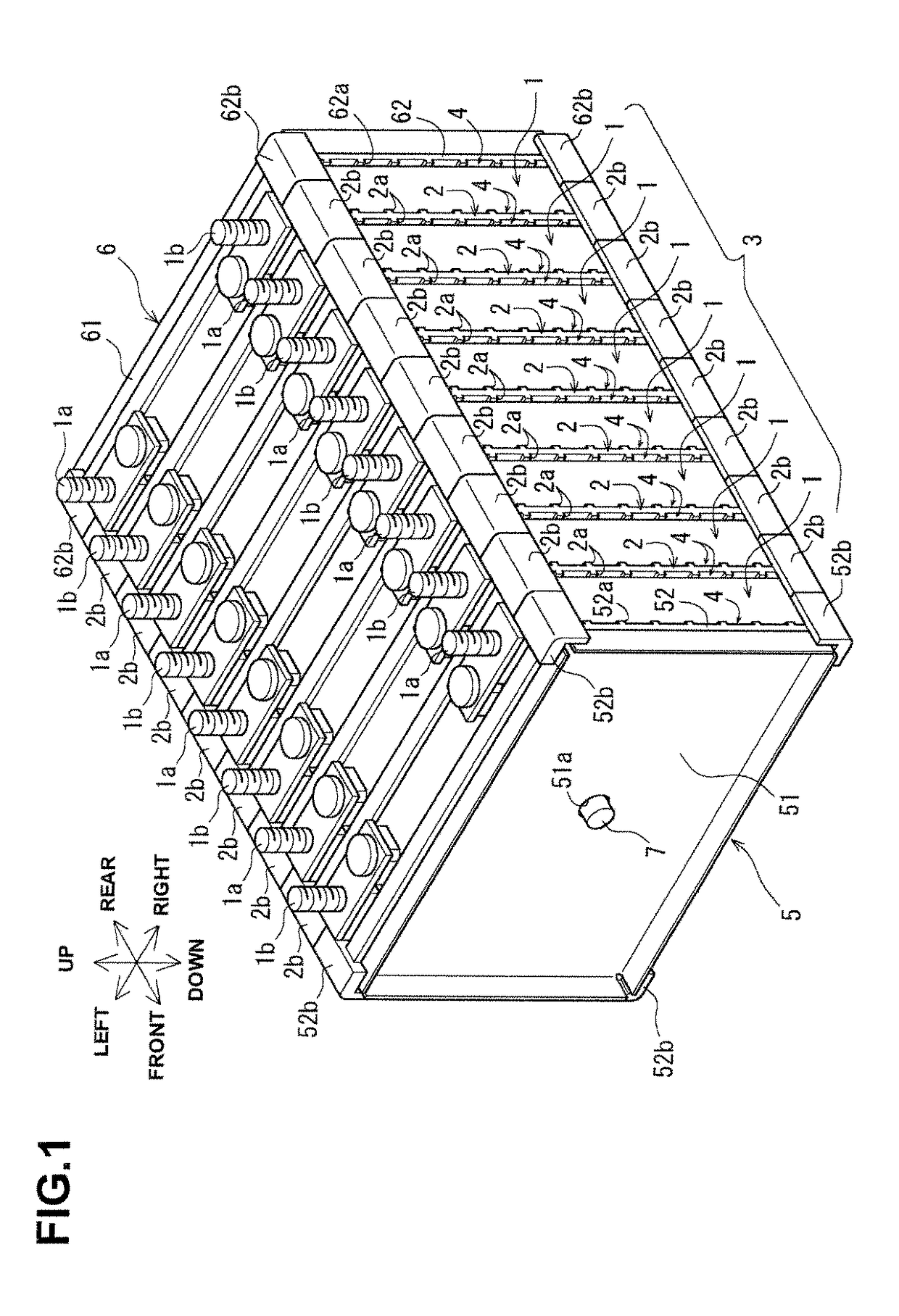
[0042]Hereinafter, an embodiment of the present invention will be described with reference to FIGS. 1 to 7.

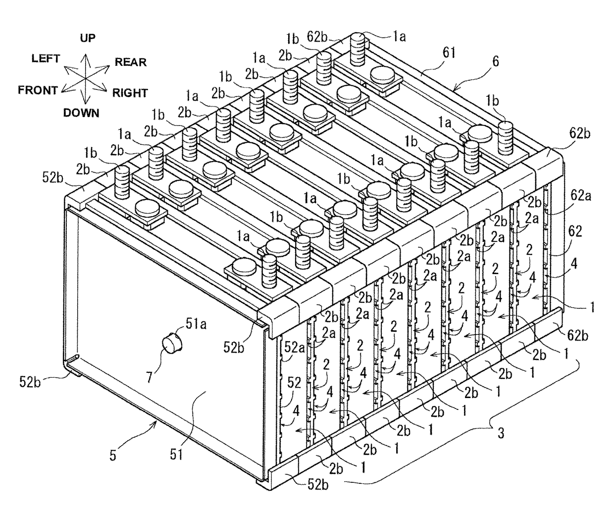
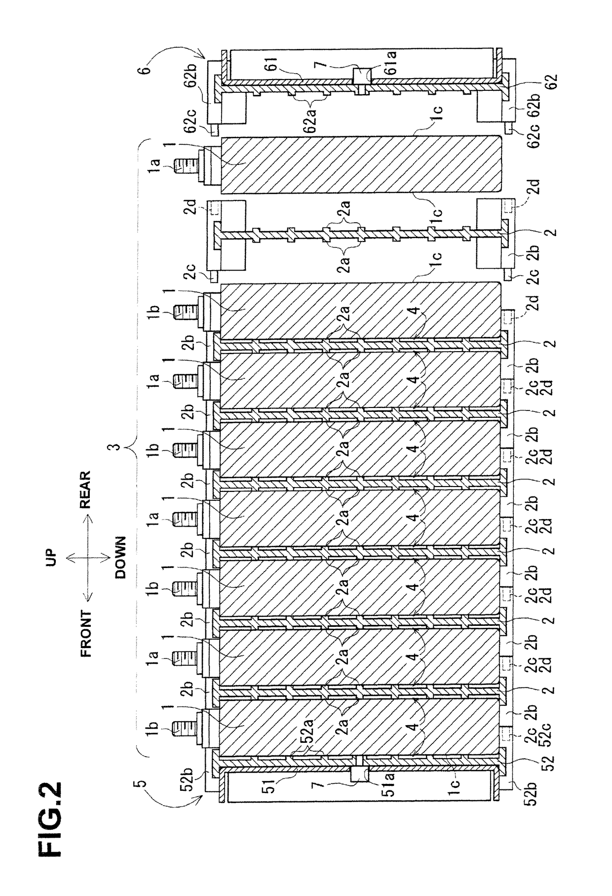
[0043]As illustrated in FIGS. 1 and 2, in a battery assembly according to the present embodiment, eight batteries 1 each serving as a rectangular non-aqueous electrolyte secondary battery are arranged. As illustrated in FIG. 3, in each battery 1, an electricity-generating element and / or a non-aqueous electrolyte are / is contained in a rectangular box type metal battery case in which its longitudinal width is shorter than its vertical height or lateral length. Further, a positive terminal 1a and a negative terminal 1b are attached to lateral ends of a lid plate constituting an upper surface of the battery case.

[0044]Since surfaces of the battery cases, which face in a longitudinal direction, serve as lateral surfaces 1c each having the largest area, the batteries 1 are arranged longitudinally in such a manner that the lateral surfaces 1c are opposed to each other and battery hold...


PUM

PropertyMeasurementUnit
insulating propertyaaaaaaaaaa
areaaaaaaaaaaa
strengthaaaaaaaaaa

Abstract

There is provided a battery assembly wherein assembly can be facilitated by reducing the number of components to be assembled, by integrally fixing resin plates (52, 62) on the inside of metal plates (51, 61) of end plates (5, 6). A laminated battery body (3) is constituted by adjacently arranging battery holders (2) made of resin forming cooling passages (4) between a plurality of batteries (1) and holding such batteries (1) on both sides between other batteries (1). The metal plates (51, 61) and resin plates (52, 62) that are integrally fixed on the inside of these metal plates are provided on the outside of the batteries (1) at both ends of the laminated battery body (3). Thus, the batteries (1) are held by the resin plates (52, 62), and the end plates (5, 6) are respectively arranged to form the cooling passages (4) between these batteries (1) and the metal plates (51, 61). The laminated battery body (3) is fixed in a clamped manner by fixing means clamping these end plates (5, 6).

Description

TECHNICAL FIELD[0001]The present invention relates to a battery assembly in which a plurality of batteries, arranged via battery holders, are fixed in a clamped manner from both sides by end plates.BACKGROUND ART[0002]In an electric vehicle or the like, a large-capacity storage battery is required, and therefore, a battery assembly in which a large number of batteries are arranged and fixed is used. Further, as such a battery assembly, there has been proposed a battery assembly in which a plurality of batteries, arranged via battery holders made of resin, are fixed in a clamped manner from both sides by end plates made of resin or metal (see Patent Document 1 and Patent Document 2, for example).[0003]The respective batteries of the foregoing battery assembly are arranged in such a manner that lateral surfaces of rectangular box type metal battery cases, each having the largest area, are opposed to each other, and battery holders made of resin are each placed between the adjacent bat...

Claims


Application Information

Patent Timeline
Patent Type & Authority Patents(United States)
IPC IPC(8): H01M2/10H01M10/6562H01M10/6563H01M10/613H01M10/6557H01M10/647H01M10/48H01M10/04H01M10/625H01M50/103H01M50/209H01M50/224H01M50/264
CPCH01M2/1077H01M10/0481H01M10/486H01M10/613H01M10/6563H01M10/647H01M10/6557H01M10/6562H01M10/625H01M50/209H01M50/224H01M50/264H01M50/103Y02E60/10Y02P70/50H01M10/658H01M10/4285H01M2220/20H01M50/593H01M10/6556H01M10/48H01M50/20H01M50/119Y02T10/70
Inventor YOSHITAKE, SHINSUKEOKAMOTO, KATSUHIKONAKAMURA, JUNSASAKI, TAKESHI
Owner GS YUASA INT LTD
Why Eureka
Try Eureka