Staple chamber assembly and linear surgical stitching device using said staple chamber assembly
a technology of staple chamber and stapler, which is applied in the field of staple cartridge assembly and linear surgical stapler, can solve the problems of refire without any nails in the reloading unit, over-deformation of nails, and insufficient wound closure, so as to eliminate the possibility of misfiring and simple structure
- Summary
- Abstract
- Description
- Claims
- Application Information
AI Technical Summary
Benefits of technology
Problems solved by technology
Method used
Image
Examples
first embodiment
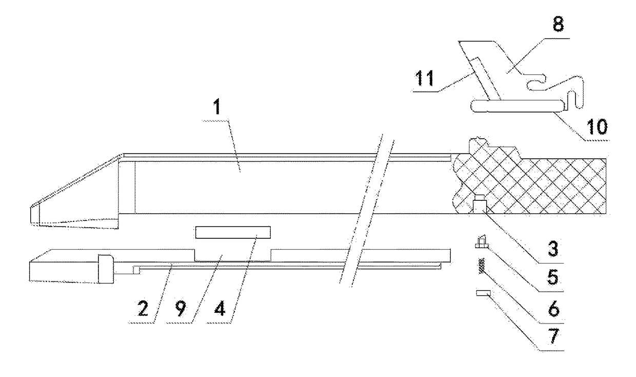
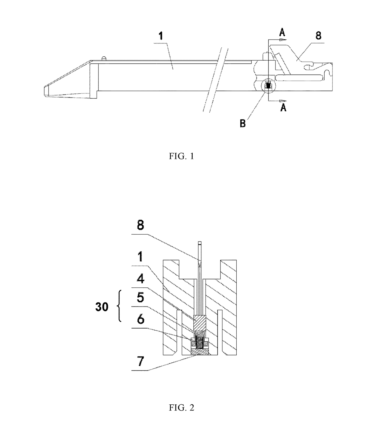
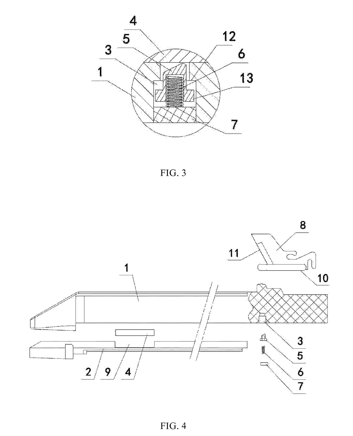
[0057]The staple cartridge 1 includes a through hole 3 located adjacent to a near-end bottom side of the staple cartridge 1. The through hole 3 is in communication with the cutting groove. According to the present application, a front-to-back direction means a left-to-right direction of the drawings, and a top-to-bottom direction means a top-to-bottom direction of the drawings. In a preferred embodiment, the through hole 3 is associated therein a moveable button 5 which is capable of reciprocating movement along an axis of the through hole. The bottom side of the moveable button 5 is provided with a spring 6. One end of the spring 6 abuts against the moveable button 5 so that the moveable button 5 always suffers a pushing force which directly tends towards the bottom surface 10. The bottom side of the spring 6 is provided with a cushion block 7 which is securely fixed to the bottom face of the staple cartridge 1. The other end of the spring 6 resists against a top surface of the cus...
second embodiment
[0062]Referring to FIGS. 5 and 6, according to the current embodiment, the elastic stopper 32 includes a rotatable block 14 pivotally mounted in the staple cartridge and a torsion spring 15 acting on the rotatable block 14. The torsion spring 15 always applies an acting force for driving the rotatable block 14 rotating clockwise. The rotatable block 14 includes a limiting surface 16 for restricting movement of a cutter-pushing rod when the staple cartridge assembly is in the firing state. The sliding block 4 is located on top of the rotatable block 14 in the initial state.
[0063]When the staple cartridge assembly is in the initial state as shown in FIG. 5, the sliding block 4 presses against the rotatable block 14. When the staple cartridge is in the firing process, the sliding block 4 is pushed to move forwardly by the cutter 8. During sliding, the sliding block 4 will fall into the predetermined recess 9 to prevent the sliding block 4 from returning back to the initial position. In...
PUM
| Property | Measurement | Unit |
|---|---|---|
| width | aaaaa | aaaaa |
| height | aaaaa | aaaaa |
| distance | aaaaa | aaaaa |
Abstract
Description
Claims
Application Information
 - R&D
- Intellectual Property
- Life Sciences
- Materials
- Tech Scout
- Unparalleled Data Quality
- Higher Quality Content
- 60% Fewer Hallucinations
Browse by: Latest US Patents, China's latest patents, Technical Efficacy Thesaurus, Application Domain, Technology Topic, Popular Technical Reports.
© 2025 PatSnap. All rights reserved.Legal|Privacy policy|Modern Slavery Act Transparency Statement|Sitemap|About US| Contact US: help@patsnap.com


