
Method of machining workpiece by cooperation of machine tool and robot

a technology of robot and workpiece, which is applied in the direction of metal-working machine components, other manufacturing equipment/tools, manufacturing tools, etc., can solve the problems of reducing machining accuracy and production efficiency, the proportion of workpieces which abut the clamp mechanism, and the inability to machin

Active Publication Date: 2018-04-10
FANUC LTD
View PDF16 Cites 1 Cited by
  • Summary
  • Abstract
  • Description
  • Claims
  • Application Information

AI Technical Summary

Problems solved by technology

When a clamp mechanism presses a work piece, which has been placed on a jig, against a clamp mechanism, the portion of the workpiece, which abuts with the clamp mechanism, cannot be machined.
In this respect, a reduction of machining accuracy and production efficiency may arise.

Method used


Image

  • Method of machining workpiece by cooperation of machine tool and robot
  • Method of machining workpiece by cooperation of machine tool and robot
  • Method of machining workpiece by cooperation of machine tool and robot

Examples


Embodiment Construction

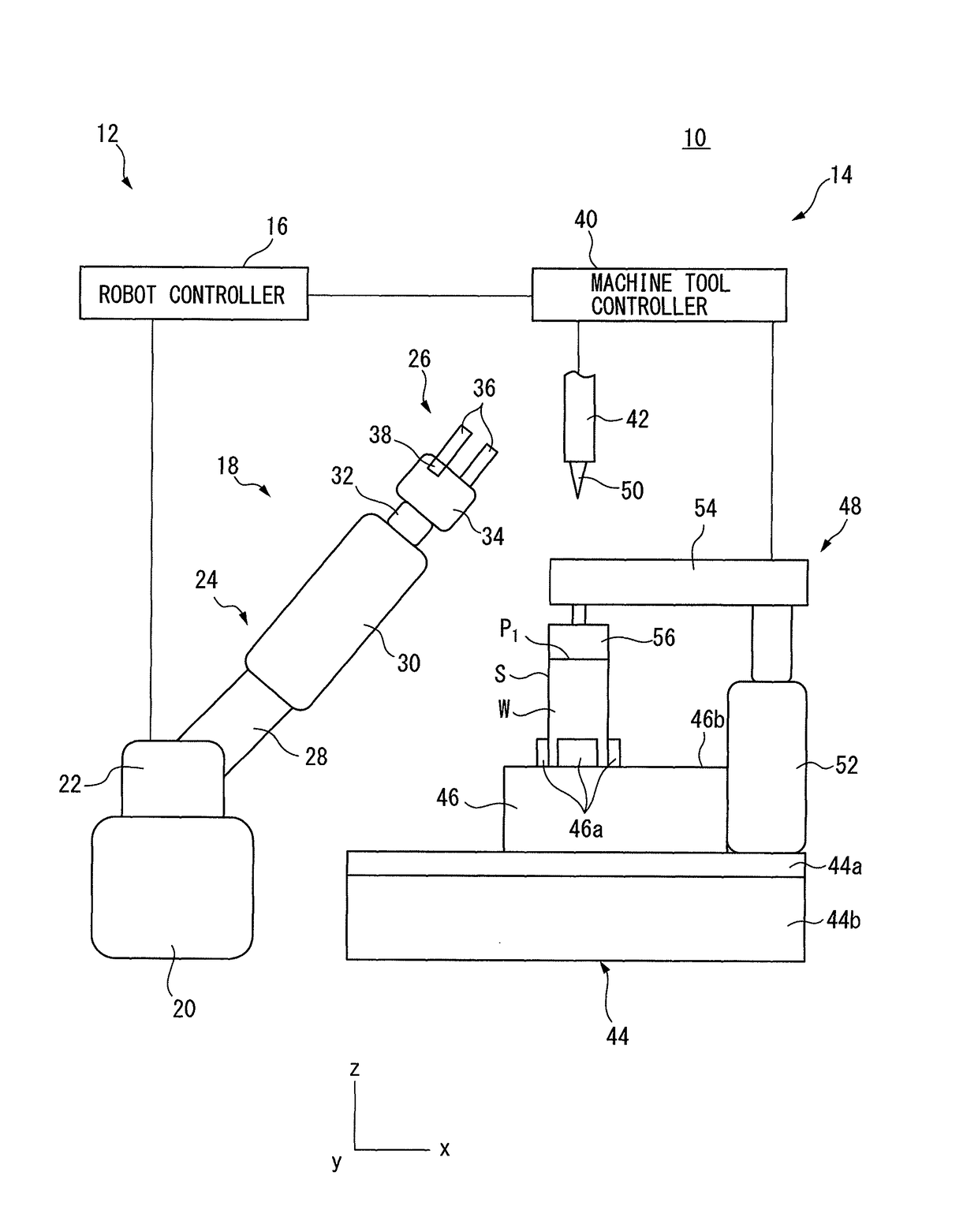
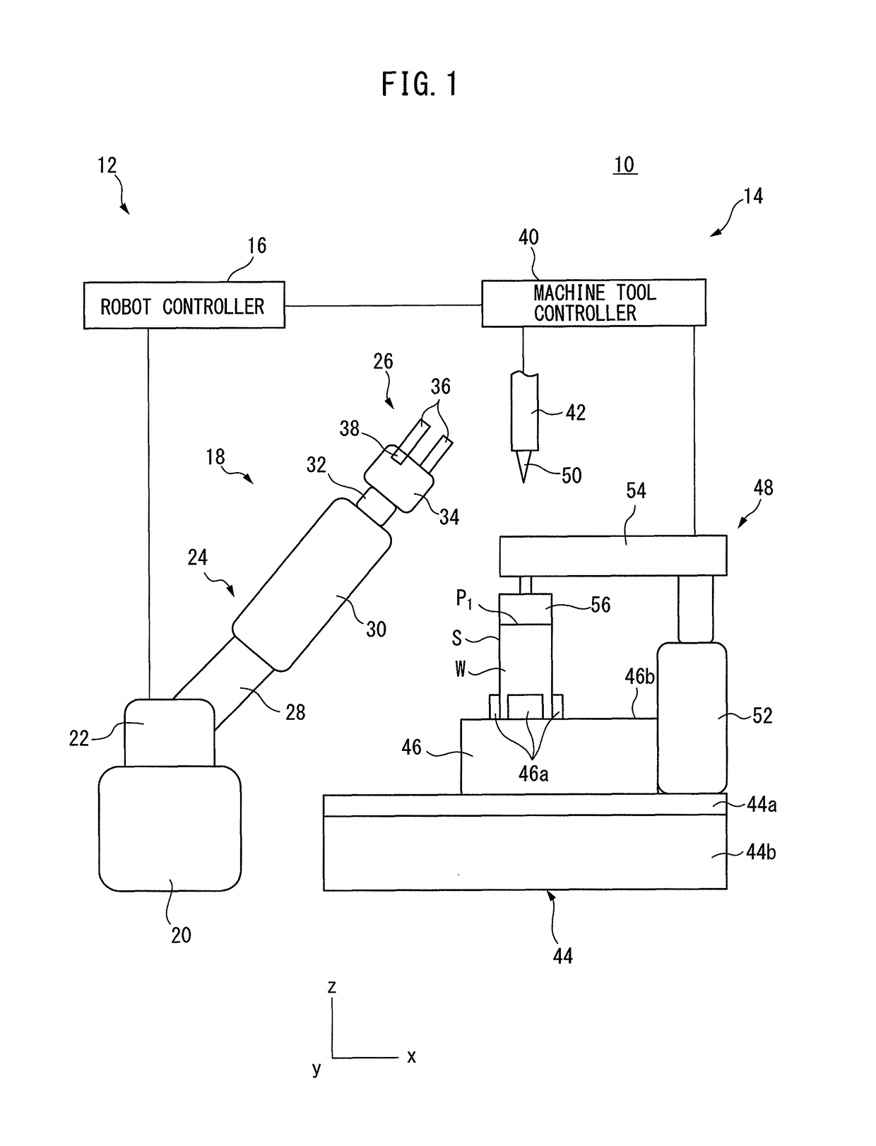
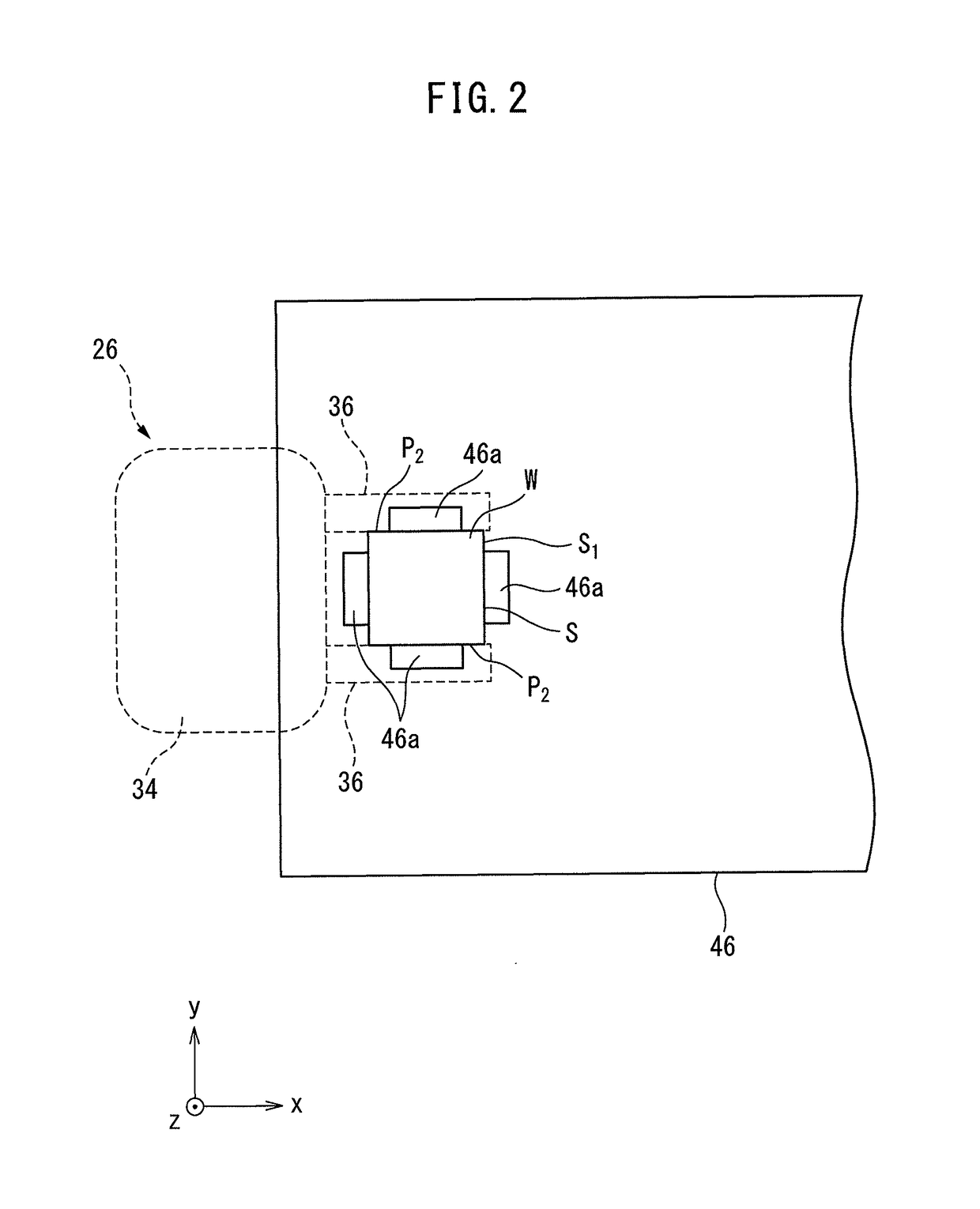
[0020]Embodiments of the invention will be described below in detail with reference to the drawings. First, with reference to FIGS. 1 and 2, a machining system 10 according to an embodiment of the invention will be described. The machining system 10 includes a robot system 12 and a machine tool 14.

[0021]The robot system 12 is for carrying a workpiece W into the machine tool 14 so as to place it on a workpiece receiving part 46 of the machine tool 14, and removing the workpiece W placed on the workpiece receiving part 46 from the machine tool 14.

[0022]The robot system 12 includes a robot controller 16 and a robot 18. The robot controller 16 includes e.g. a central processing unit (CPU) and a memory (both are not shown), and directly or indirectly controls each component of the robot 18.

[0023]The robot 18 is e.g. a vertical articulated robot, and includes a robot base 20, a revolving drum 22, a robot arm 24, a robot hand 26, and a force sensor 38. The robot base 20 is fixed on a floor...


PUM

PropertyMeasurementUnit
forceaaaaaaaaaa
force sensoraaaaaaaaaa
timeaaaaaaaaaa

Abstract

A method for machining a workpiece which can prevent a reduction in machining accuracy and production efficiency. The method includes pressing a clamp part against a first portion of the workpiece, to clamp the workpiece in cooperation with a workpiece receiving part, causing the clamp part to move away from the first portion, to release the workpiece, which has been clamped by the clamp part, operating a robot to cause a robot hand to grasp a second portion of the workpiece, which is different from the first portion, to restrict the movement of the workpiece relative to the workpiece receiving part without a change in the posture of the workpiece, and operating a machine tool to machine the first portion while restricting the movement of the workpiece relative to the workpiece receiving part.

Description

BACKGROUND OF THE INVENTION[0001]1. Field of the Invention[0002]The invention relates to a method of machining a workpiece by cooperation of a machine tool and a robot.[0003]2. Description of the Related Art[0004]A machining system provided with a robot which grasps and transfers a workpiece, and places the workpiece on a jig has been known (see, for example, Japanese Unexamined Patent Publication (Kokai) No. 2009-184055). Further, a machine tool provided with a clamp mechanism for clamping a workpiece, to machine the workpiece placed on a jig has been known (see, for example, Japanese Unexamined Patent Publication (Kokai) No. 9-201742).[0005]When a clamp mechanism presses a work piece, which has been placed on a jig, against a clamp mechanism, the portion of the workpiece, which abuts with the clamp mechanism, cannot be machined. Thus, conventionally, in order to machine this portion, another operation, for example, placing the workpiece on another jig is necessary in some cases. I...

Claims


Application Information

Patent Timeline
Patent Type & Authority Patents(United States)
IPC IPC(8): B23P23/04B23Q17/00B25J13/08B23Q3/06B23Q7/04
CPCB23P23/04B23Q3/069B23Q7/047B25J13/085Y10T29/49998B23C2270/08B23Q17/005B23Q2703/00B23C2220/48
Inventor MATAKE, KAZUYOSHI
Owner FANUC LTD
Learn More