Manifold driver

a technology of manifold and driver, which is applied in the field of fluid control and processing system, can solve the problems of complex interface between such a cartridge and the instrument that operates it, fluid cross contamination risk, leakage and wear, etc., and achieve the effect of not offering satisfying solutions for the control of the pump and/or the valv

Active Publication Date: 2018-04-10
BIOCARTIS NV
View PDF12 Cites 0 Cited by
  • Summary
  • Abstract
  • Description
  • Claims
  • Application Information

AI Technical Summary

Benefits of technology

[0005]The present invention aims to remedy all or part of the disadvantages mentioned above. In particular, the present invention aims at providing a fluid control and processing system that is simple, reliable, accurate and avoids contamination of the instrument.
[0018]Thus, the fluid control and processing system according to the present invention solves the technical issues mentioned above by providing reversible fastening means for fastening the piston to the piston driver. Indeed, the piston and the piston driver can be bound together, when the instrument is operating the cartridge, so that the piston driver from the instrument can control the movement of the piston received in the cylinder body of the cartridge. When the piston driver is fastened to the piston via the reversible fastening means, the piston is movable around an axis A extending along the piston driver. Thus, in the system according to the present invention the piston driver can control the movement of the piston both in rotation and in translation around a single axis A. If the cartridge comprises a plurality of cylinder bodies, each cylinder body comprising a cylinder and a piston movable in said cylinder, each piston is movable around the axis extending along the piston driver fastened to the piston received in each cylinder. Thus, the instrument operating the cartridge is capable of modulating individually the fluid volume inside each cylinder by moving the piston around the axis extending along the piston driver fastened to said piston received in each cylinder. Moreover, the rotating means for rotating the cylinder body in respect with the cartridge allow the control of the position of the fluid port with respect to the dispensing ports. The fluid control and processing system according to the present invention further offers flexibility since several cartridges can be operated successively by a given instrument as the fastening means are reversible and therefore allow the piston of the cartridge and the piston driver of the instrument to be unfastened.
[0021]According to an embodiment of the invention, the fastening means are designed for fastening the piston with the piston driver when the piston driver is rotated with respect to the piston in a first direction; and are designed for unfastening the piston from the piston driver when the piston driver is rotated with respect to the piston in a second direction opposite to the first direction. Thus, when cartridge is operated by the instrument, a rotation in the first direction of the piston driver with respect to the piston permits the fastening of the cartridge with the instrument via the fastening means; a subsequent translation of the piston driver permits the control of the piston. The rotation in the opposite direction of the piston driver with respect to the piston permits to uncouple the cartridge and the instrument. Such fastening means hence offer flexibility. Such fastening means do not require complex mechanisms.
[0022]In an embodiment of the present invention, the fastening means comprise a bayonet mount. Such a bayonet mount is simple and requires a limited number of technical parts. With such a bayonet mount, the coupling and uncoupling are swift and require rotating the piston driver by a low angle.
[0024]In an embodiment of the present invention, the interlocking means are designed for preventing the rotation of the piston driver with respect to the piston in the second direction. Such interlocking means, once engaged, prevent the disconnection of the fastening means. Rotation of the interlocking means permits to rotate the rotating means and the piston driver at the same time.

Problems solved by technology

The pumps and or valves embedded in an instrument that controls the cartridges present several drawbacks, such as risks of fluid cross contaminations, leakages and wear.
The interface between such a cartridge and an instrument that operate it is complex and present several drawbacks with respect to accuracy and reliability.
The existing cartridges and instruments do not offer satisfying solutions with respect to the control of the pumps and / or valves and there is a need for cartridges and instruments that offer a simple, accurate and reliable fluid control.

Method used


Image

  • Manifold driver
  • Manifold driver
  • Manifold driver

Examples


Embodiment Construction

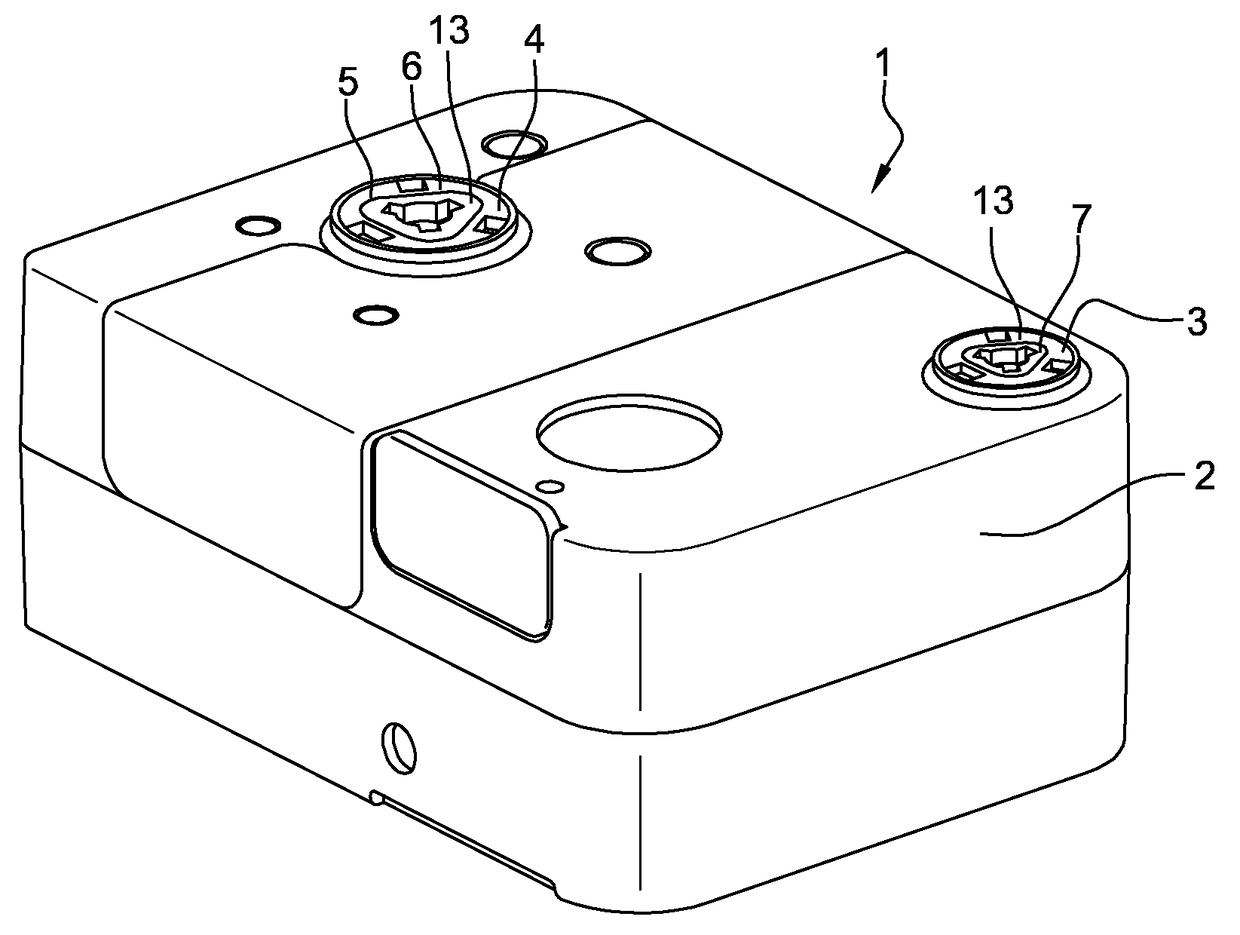
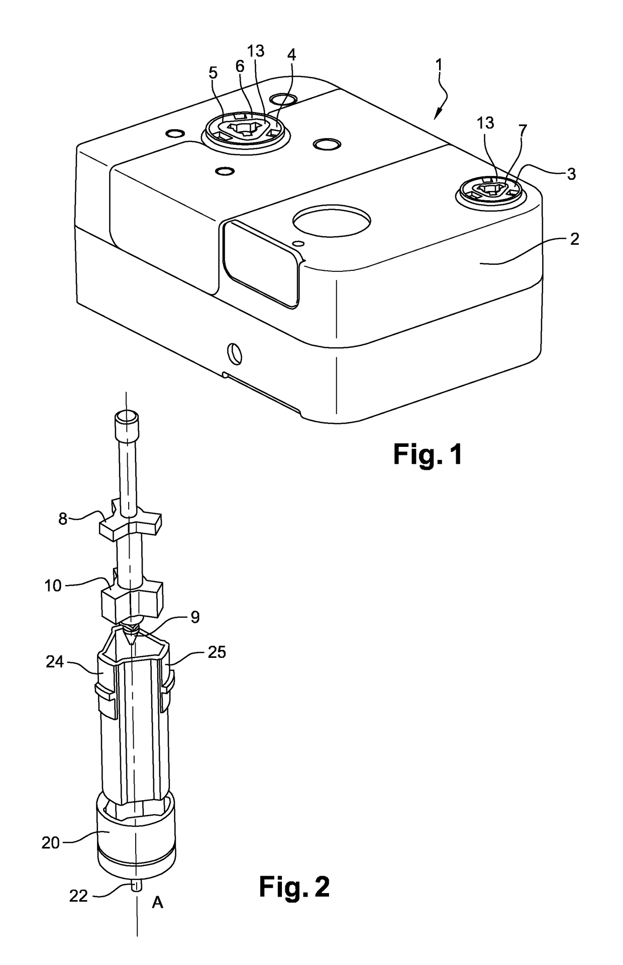
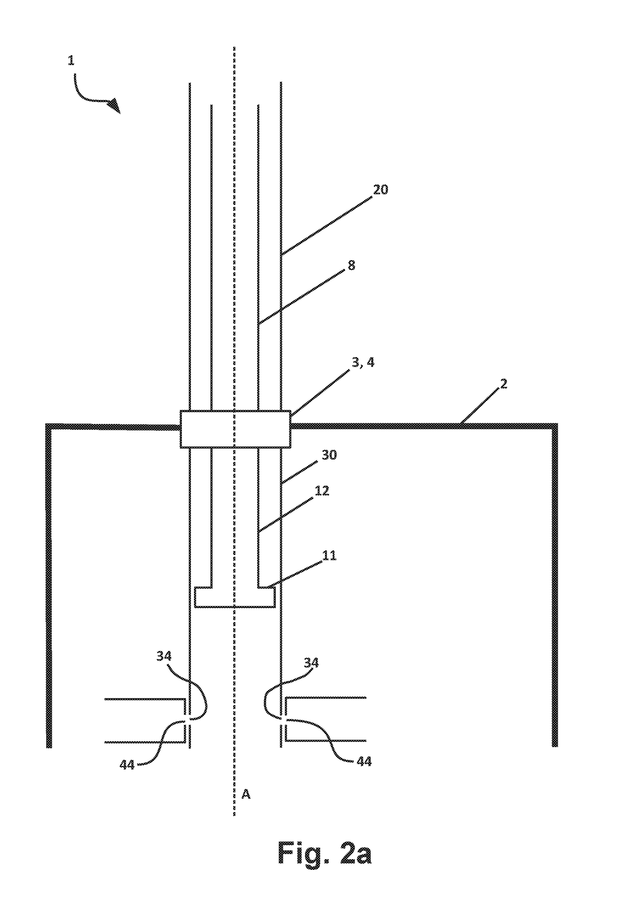
[0041]A fluid control and processing system 1, partially illustrated in FIGS. 1 to 7, according to the present invention comprises a cartridge 2 shown in FIG. 1. The cartridge 2 is designed for being operated by an instrument partially shown in figures. In an illustrated embodiment, cartridge 2 is adapted to receive two cylinder bodies 30. Each cylinder body 30 presents a cylinder interface 3, 4 attached to one of the extremities of the cylinder body 30, so that said cylinder interface 3, 4 is accessible from the outside of the cartridge 2. Each cylinder interface 3, 4 has a shape of a hollow right circular cylinder 5 (FIGS. 1, 3, 4, 5 and 6) presenting a circular bearing surface 6, 7 forming the external surface of said cylinder interface 3, 4. Each cylinder body 30 comprises a cylinder and at least a fluid port 34, in fluid communication with said cylinder.

[0042]The fluid control and processing system 1 further comprises dispensing ports 44, to drive at least a fluid flow. Each di...


PUM

PropertyMeasurementUnit
volumeaaaaaaaaaa
rotationaaaaaaaaaa
movementaaaaaaaaaa

Abstract

A fluid control and processing system comprising a cartridge and an instrument for operating the cartridge. The cartridge comprises a cylinder body comprising a cylinder and a fluid port. It further comprises dispensing ports to drive a fluid flow, each dispensing port being positioned to be connectable, when the instrument is operating the cartridge, with at least a fluid port by rotation of the cylinder body. The instrument comprises a piston driver for driving the piston. The system further comprises: reversible fastening means for fastening the piston when the piston driver is rotated with respect to the piston, so that the movement of the piston is controlled by the piston driver; and rotating means comprising a cylinder driver constitutive of the instrument for rotating the cylinder body around the axis A.

Description

FIELD OF THE INVENTION[0001]The present invention relates to a fluid control and processing system comprising a cartridge and an instrument designed for operating the cartridge.BACKGROUND OF THE INVENTION[0002]Analysis of environmental or clinical fluids usually involves multiple step processes, from chemical to thermal or acoustical treatments of the sample. Such protocols are sometimes performed in disposable cartridges that involve microfluidic processes and that comprise for these purposes different inner parts such as fluid containers, reaction chambers, fluid analyzers, microchannels, etc. . . . The movement of the fluids, reagents and liquefied samples, between the different inner parts requires fluid pumps and / or valves. These pumps and / or valves are either enclosed in instruments that are designed for receiving and operating said cartridges or are embedded in the cartridges. The pumps and or valves embedded in an instrument that controls the cartridges present several drawb...

Claims


Application Information

Patent Timeline
Patent Type & Authority Patents(United States)
IPC IPC(8): F16K27/04F16K3/02B01L3/00F16K3/30G01N35/10G01N35/00
CPCF16K27/04F16K3/0218F16K3/30G01N35/0099G01N35/1009B01L3/502715B01L2400/0644B01L2200/025B01L2200/027B01L2200/04B01L2300/049B01L2300/087B01L2300/0809B01L2300/0832B01L2400/0478
Inventor KROON, GERARDDE GIER, RONALD
Owner BIOCARTIS NV
Why Eureka
Try Eureka