Unlock instant, AI-driven research and patent intelligence for your innovation.

Refrigeration device

a refrigeration device and refrigeration technology, applied in refrigeration machines, lighting and heating apparatus, refrigeration safety arrangements, etc., can solve the problems of increasing the power consumed by the refrigeration device, and achieve the effect of reducing the cost, reducing the power consumption, and simplifying the control

Active Publication Date: 2018-04-10
DAIKIN IND LTD
View PDF21 Cites 6 Cited by
  • Summary
  • Abstract
  • Description
  • Claims
  • Application Information

AI Technical Summary

Benefits of technology

The present invention provides a refrigeration device that uses a control method based on the saturation temperature and predetermined temperature to simplify the control and minimize costs. The device can maintain an appropriate oil concentration or viscosity, and achieve a cut in standby power. Additionally, the device can respond quickly to changes in situations, suppress an increase in calculation region, and improve reliability. Overall, the invention provides a more efficient and reliable refrigeration device.

Problems solved by technology

However, energizing the heater to warm the compressor presents a problem in that a given amount of power (standby power) is consumed, increasing the amount of power consumed by the refrigeration device.

Method used


Image

  • Refrigeration device
  • Refrigeration device
  • Refrigeration device

Examples


first embodiment

(1) Configuration of Refrigeration Device

[0046](1-1) Refrigerant Circuit

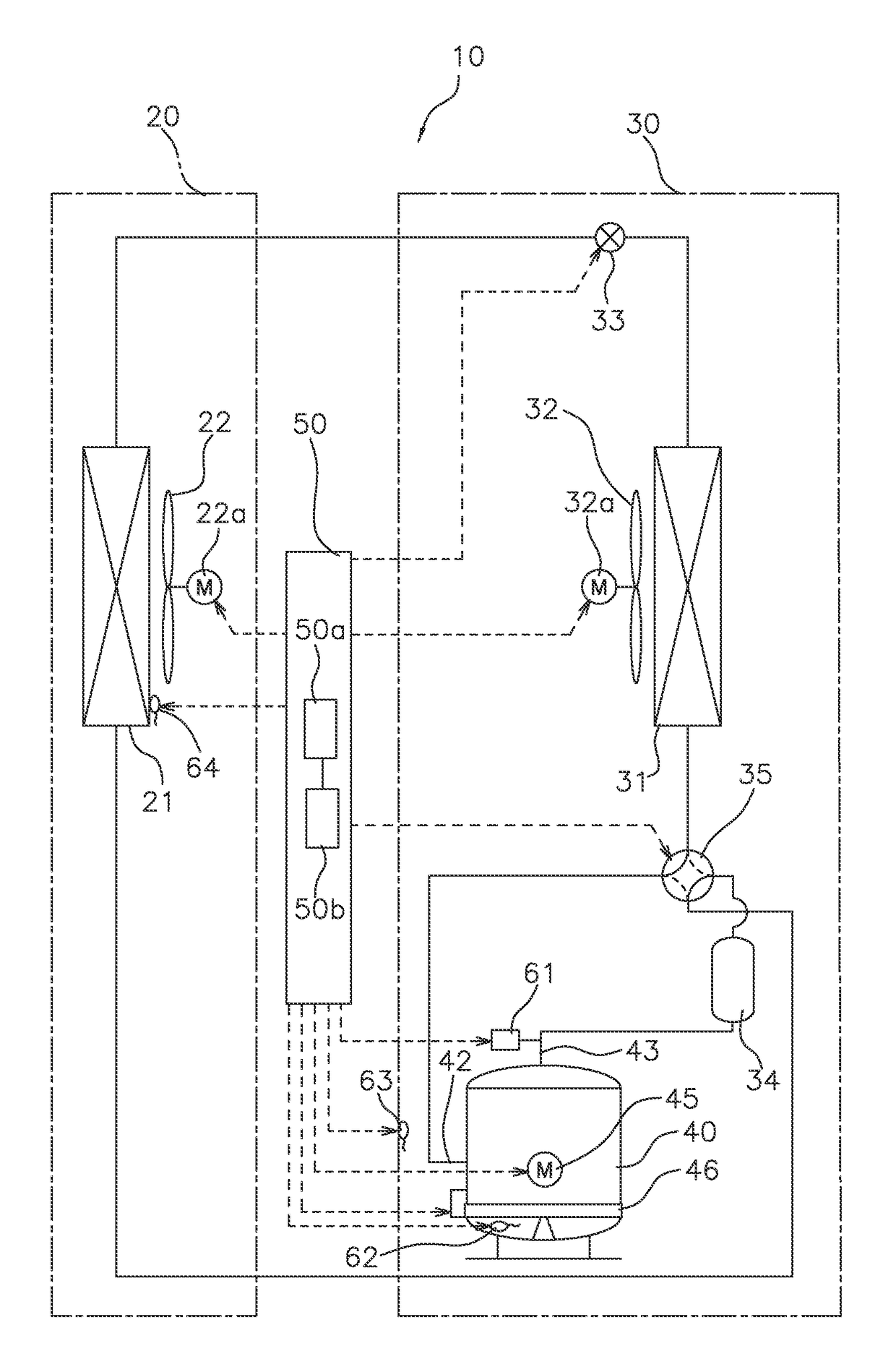
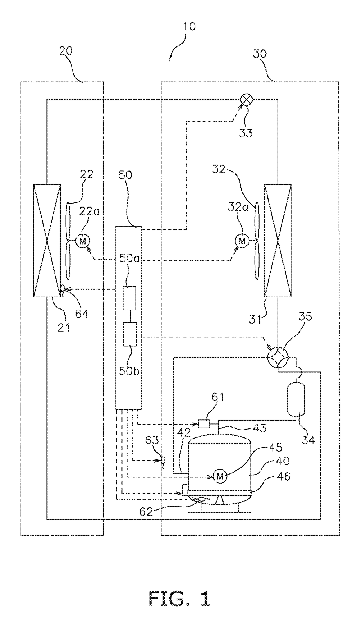
[0047]FIG. 1 is a refrigerant circuit diagram showing the configuration of an air-conditioning device 10 in which a refrigeration device according to a first embodiment of the present invention is employed. The air-conditioning device 10 comprises a usage-side unit 20 installed indoors, and a heat-source-side unit 30 installed outdoors. An indoor heat exchanger 21 and an indoor fan 22 are disposed in the usage-side unit 20. An outdoor heat exchanger 31, an outdoor fan 32, an electric valve 33, an accumulator 34, a four-way switching valve 35, and a compressor 40 are disposed in the heat-source-side unit 30.

[0048]The air-conditioning device 10 in FIG. 1 comprises the four-way switching valve 35, and the four-way switching valve 35 enables switching between a cooling operation in which the indoor space is cooled and a heating operation in which the indoor space is heated. During a cooling operation, the indoor hea...

second embodiment

(6) Overview of Refrigeration Device

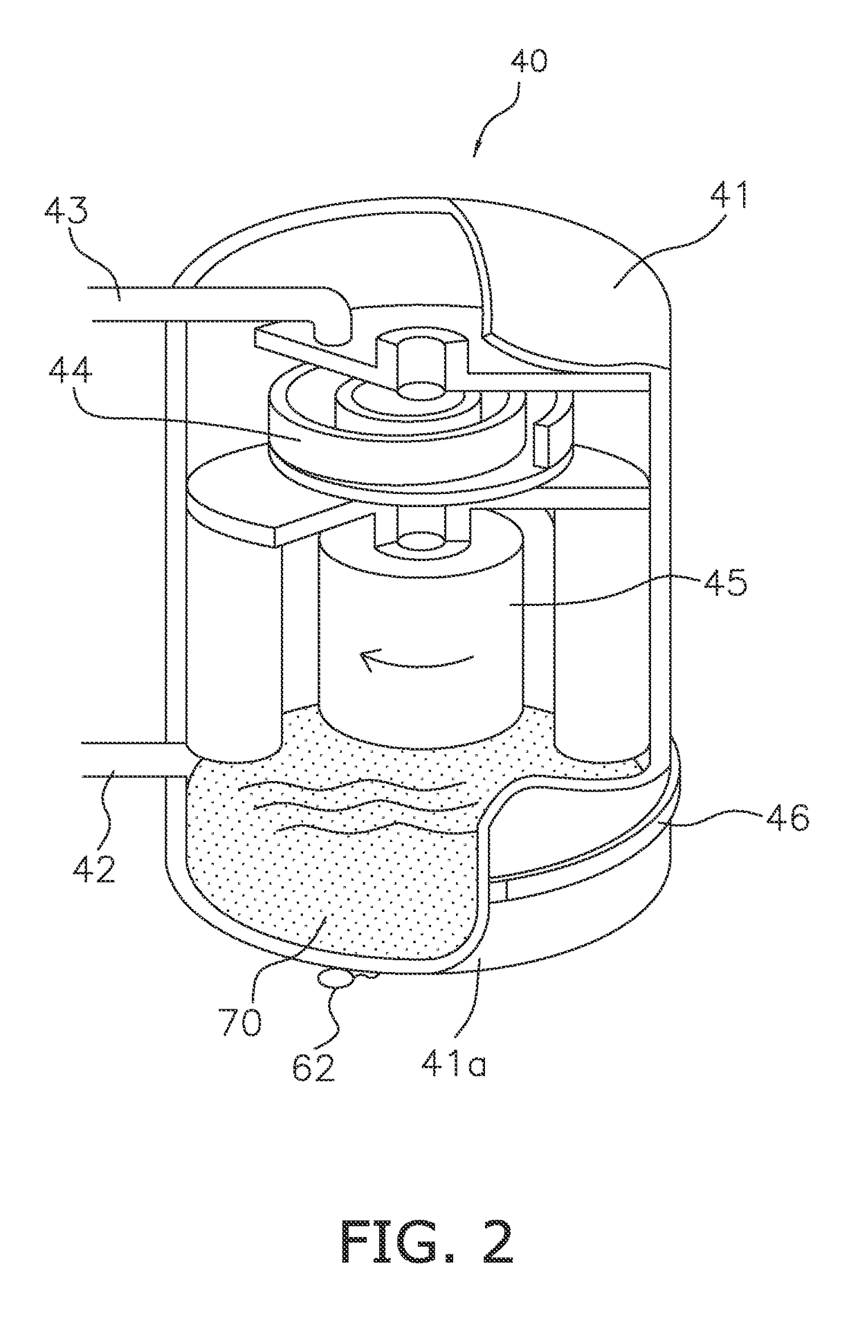
[0095]In the first embodiment above, a description was given with regards to controlling the heater while the refrigeration device of the air-conditioning device 10 is being supplied with power and the refrigeration device of the air-conditioning device 10 is maintaining an power-on state. However, situations in which the refrigeration device of the air-conditioning device 10 may be placed include a state in which the power supply of the air-conditioning device 10 is cut. In a compressor 40 that is stopped for a long period of time in a state in which the power supply is cut, the refrigeration oil in the compressor 40 cannot be heated, and a large amount of the refrigerant may solve into the refrigeration oil due to a change in the external air temperature. An air-conditioning device 10 according to a second embodiment described below is configured so as to make it possible to perform a control to prevent defects caused by a decrease in viscosity ...

modification examples

(8) Modification Examples

[0110](8-1)

[0111]In the second embodiment above, even when it is determined in step S33 that the test operation has been completed, the state after the stoppage is not known; therefore, special start-up is performed instead of normal start-up. However, it is possible to further apply, with regards to the special start-up, the high-level special start-up set in step S37.

[0112]In addition, when the condition for entering step S35 is satisfied, a measure for increasing the target oil concentration can also be taken.


PUM


Abstract

A refrigeration device includes a radiator, an evaporator, a compressor, a heater and a control device. The radiator causes a refrigerant to radiate heat. The evaporator causes the refrigerant to evaporate. The compressor compresses the refrigerant circulating between the radiator and the evaporator. The heater heats lubricating oil in the compressor. The control device controls the heater so that an oil temperature of the lubricating oil in the compressor reaches an oil temperature target value obtained by adding a predetermined temperature to saturation temperature of the refrigerant in the compressor.

Description

CROSS-REFERENCE TO RELATED APPLICATIONS[0001]This U.S. National stage application claims priority under 35 U.S.C. § 119(a) to Japanese Patent Application Nos. 2011-218390, filed in Japan on Sep. 30, 2011, and 2012-213551, filed Sep. 27, 2012, the entire contents of which are hereby incorporated herein by reference.TECHNICAL FIELD[0002]The present invention relates to a refrigeration device in which a refrigerant is compressed by a compressor.BACKGROUND ART[0003]Conventionally, as air-conditioning devices for transferring heat between indoors and outdoors, there have been air-conditioning devices comprising a usage-side heat exchanger disposed indoors and a heat-source-side heat exchanger disposed outdoors. In an air-conditioning device of such description, in order to transfer heat, one of the usage-side heat exchanger and the heat-source-side heat exchanger is used as a radiator, and the other is used as an evaporator. For example, in air-conditioning devices of such description, a...

Claims


Application Information

Patent Timeline
Patent Type & Authority Patents(United States)
IPC IPC(8): F25B1/00F25B49/02F25B49/00F25B31/00F25B45/00
CPCF25B49/02F25B31/002F25B2400/01F25B2500/26F25B2700/21155F25B2700/193F25B2700/1933F25B2700/2105F25B2500/31
Inventor YURA, YOSHINORIKASAHARA, SHINICHIKIBO, KOUSUKE
Owner DAIKIN IND LTD