Actuator fault detection device, controlling device and control method

a technology of fault detection and control device, applied in the direction of electric controllers, furniture, instruments, etc., can solve the problem that the position does not always actually happen

Active Publication Date: 2018-04-17
YAMATAKE HONEYWELL CO LTD
View PDF12 Cites 0 Cited by
  • Summary
  • Abstract
  • Description
  • Claims
  • Application Information

AI Technical Summary

Benefits of technology

[0025]According to an embodiment of the present invention, the value of the actuator position MP is acquired from the position detection and feedback mechanism, and the follow-up difference DM between the manipulation variable MV and the actuator position MP is calculated. It is determined whether the high speed operation of the actuator departs from the allowable range based on the change rate ΔMP of the actuator position MP and the follow-up difference DM, thereby being capable of detecting or predicting the fault of the actuator with accuracy higher than that of the conventional art.
[0026]Further, according to an embodiment of the present invention, the value of the actuator position MP is acquired from the position detection and feedback mechanism, and the follow-up difference DM between the manipulation variable MV and the actuator position MP is calculated. It is determined whether the low speed operation of the actuator departs from the allowable range based on the change rate ΔMV of the manipulation variable MV, the change rate ΔMP of the actuator position MP and the follow-up difference DM, thereby being capable of detecting or predicting the fault of the actuator with accuracy higher than that of the conventional art.

Problems solved by technology

However, since the motor is constrained by a movable body whose operating speed is limited, the motor position does not always actually follow the manipulation variable MV calculated by the PID calculation.

Method used


Image

  • Actuator fault detection device, controlling device and control method
  • Actuator fault detection device, controlling device and control method
  • Actuator fault detection device, controlling device and control method

Examples


embodiment

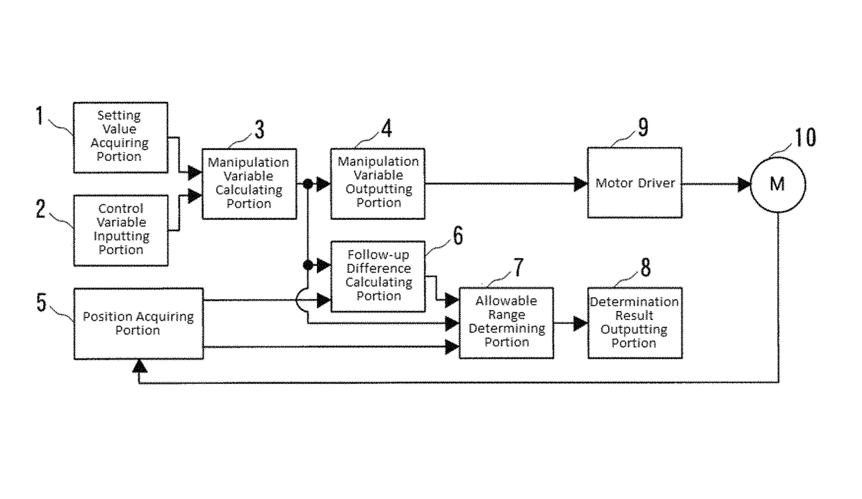
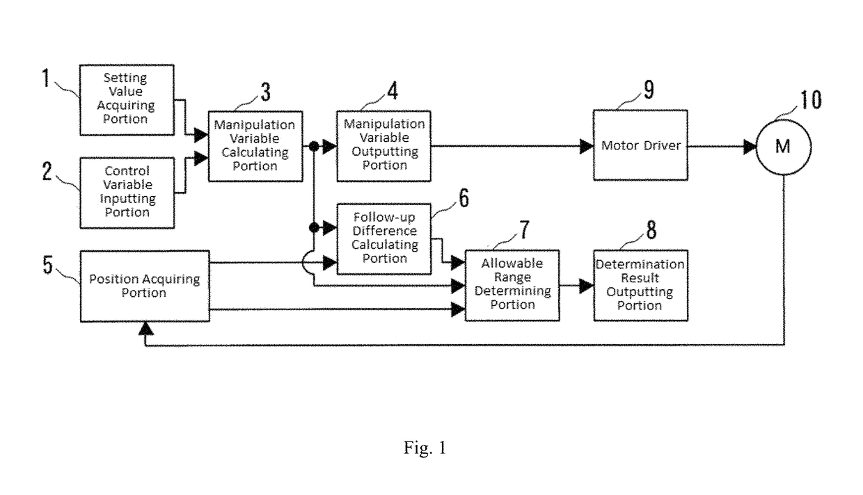
[0034]FIG. 1 is a block diagram illustrating a configuration of a controlling device according to an embodiment of the present invention. In this embodiment, a fault detection system for a motor for operating a control valve of a gas flow rate regulator for controlling a flow rate of a fuel in a temperature control system for combustion based furnace is presented.

[0035]A controlling device includes a setting value acquiring portion 1, a control variable inputting portion 2 that receives a controlled variable PV from a measuring instrument, a manipulation variable calculating portion 3 that calculates a manipulation variable MV based on a setting value SP and the controlled variable PV through a PID control operation, and a manipulation variable outputting portion 4 that outputs the manipulation variable MV to a motor driver 9. The controlling device also includes a position acquiring portion 5 that acquires a value of a motor position MP from an encoder for detecting a position of a...


PUM


Abstract

An actuator fault detection device that detects a fault of an actuator driven according to a manipulation variable MV output from a controlling device, including: a position acquiring portion that acquires a value of a motor position MP from a detector that detects a position of an actuator corresponding to a manipulation variable MV; a follow-up difference calculating portion that calculates a follow-up difference DM=MV−MP; and an allowable range determining portion that determines whether or not high speed operation or low speed operation of the actuator departs from an allowable range based on a manipulation variable change rate ΔMV, an actuator position change rate ΔMP, and the follow-up difference DM.

Description

CROSS-REFERENCE TO RELATED APPLICATION[0001]The present application claims the benefit of and priority to Japanese Patent Application No. 2015-150495, filed on Jul. 30, 2015, the entire contents of which are incorporated by reference herein.TECHNICAL FIELD[0002]The present invention relates to an actuator fault detection device capable of detecting or predicting a fault of an actuator such as a motor or a valve, and a controlling device having the actuator fault detection device.BACKGROUND ART[0003]A hybrid heat treatment furnace including a gas combustion furnace and an electric furnace has been developed for the purpose of satisfying as much as possible the requirements of energy saving and high precision control. The hybrid heat treatment furnace operates as follows.[0004](I) The hybrid heat treatment furnace operates the energetically favorable gas combustion furnace when raising a temperature from a lower temperature to a higher temperature.[0005](II) The hybrid heat treatment ...

Claims


Application Information

Patent Timeline
Patent Type & Authority Patents(United States)
IPC IPC(8): G01R31/34F27D21/04
CPCF27D21/04G01R31/34G01M13/00G05B11/42G05B23/0218G05B23/0235
Inventor TANAKA, MASATOSUGAWARA, FUMIHIROAIKAWA, TOMOHIKO
Owner YAMATAKE HONEYWELL CO LTD
Why Eureka
Try Eureka