Detecting apparatus and detecting method thereof

a detection apparatus and optical field technology, applied in the field of detecting apparatus and detecting method, can solve the problem of very expansive cost, and achieve the effect of reducing cost and fast and convenient detection

Inactive Publication Date: 2018-04-24
NAT CENT UNIV
View PDF40 Cites 0 Cited by
  • Summary
  • Abstract
  • Description
  • Claims
  • Application Information

AI Technical Summary

Benefits of technology

[0009]In view of the foregoing, an objective of the present invention is to provide a detection apparatus and a detection method that can detect the optical field distribution and total flux of a light source with low cost and high accuracy (compared with the conventional photometer and integrating sphere).
[0042]As mentioned above, the detecting apparatus and method of the invention detects an object disposed adjacent to the first surface of the screen, and the detecting unit is disposed corresponding to the object and located adjacent to the second surface of the screen. Besides, the holding unit holds the relative distances between the screen, the object and the detecting unit, and the detecting unit captures the image of the second surface of the screen for calculating the optical field distribution of the object. Accordingly, the detecting unit can capture the optical field distributions of the light emitted by the object from different angles or directions, thereby obtaining the optical field distributions of the object in at least half-sphere domain. Therefore, the detecting apparatus and method of the invention can replace the commercialized goniophotometer and integrating sphere, and have the advantages of fast and convenient detection and lower cost.
[0043]Moreover, regarding to the application, the detecting apparatus of the invention can further replace the conventional method for detecting the total flux of the light source by the integrating sphere. After some proper modifications, the detecting apparatus of the invention can further the BSDF of an optical film.

Problems solved by technology

Although this new detection apparatus has the advantages of fast detection and short detection time, however, it needs a coating with perfect Lambertian property, so the cost is very expansive.

Method used


Image

  • Detecting apparatus and detecting method thereof
  • Detecting apparatus and detecting method thereof
  • Detecting apparatus and detecting method thereof

Examples


first embodiment

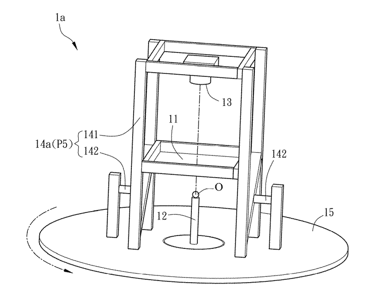
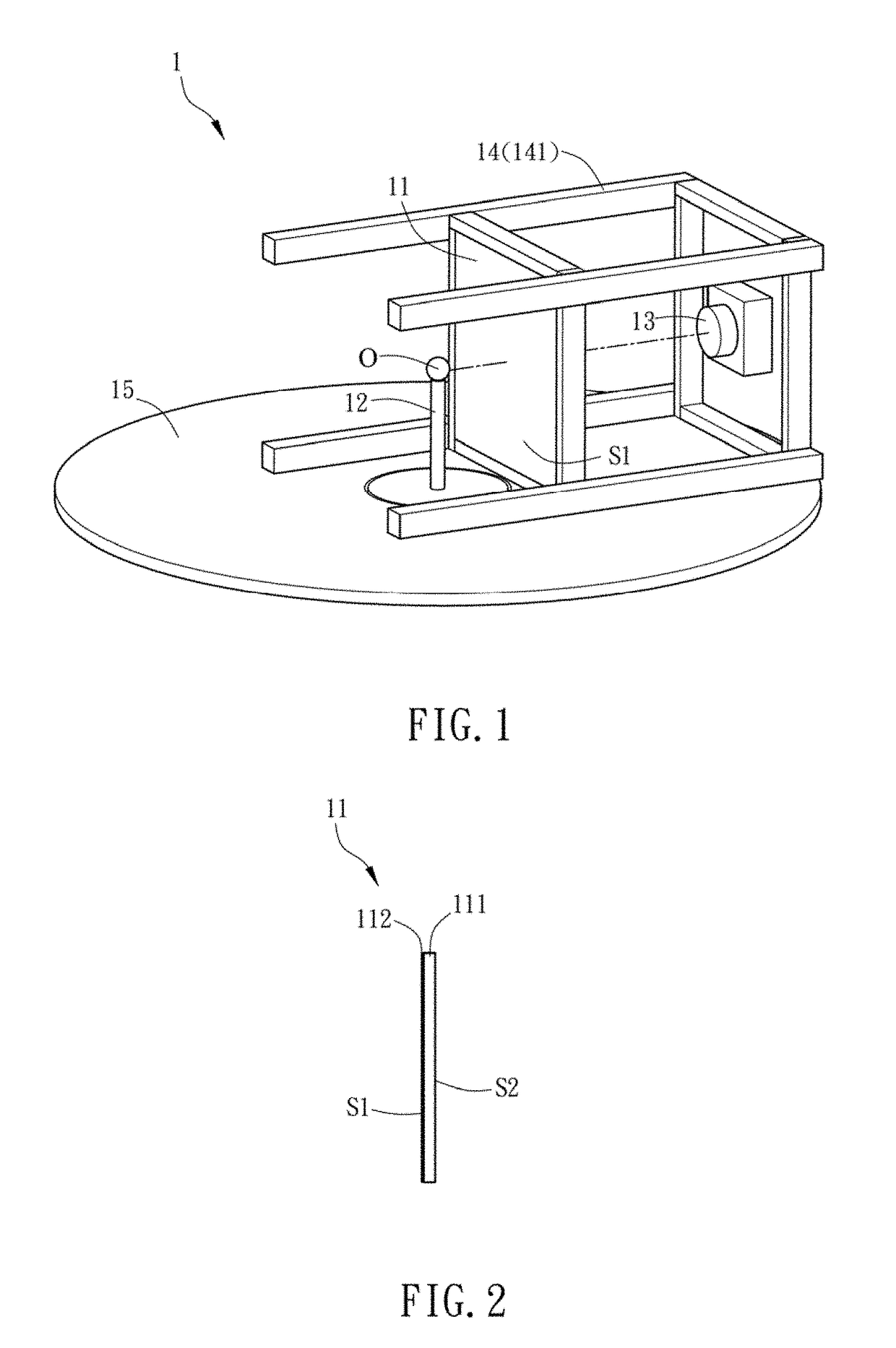
[0060]FIG. 1 is a schematic diagram of a detecting apparatus 1 according to the invention. With reference to FIG. 1, a detecting apparatus 1 of the invention is used for detecting an object and includes at least a screen 11, a carrier 12 for carrying the object, at least a detecting unit 13, and at least a holding unit 14. In this embodiment, the detecting apparatus 1 includes a screen 11, a detecting unit 13, and a holding unit 14. To be noted, the object to be detected is, for example, an optical film or a light source, such as LED, OLED, CCFL or HCFL. Besides, the object can be a light emitting element, a light source module, or an illumination device. Otherwise, the object to be detected can be an optical film such as a diffusion sheet (plate), a brightness enhancement film (BEF), a prism, or any other optical components. In this embodiment, as shown in FIG. 1, the object to be detected is a LED device O, and the carrier 12 carries the LED device O and has the driving circuit (n...

second embodiment

[0107]FIGS. 9A and 9B are schematic diagrams of a detecting apparatus 2 according to the invention.

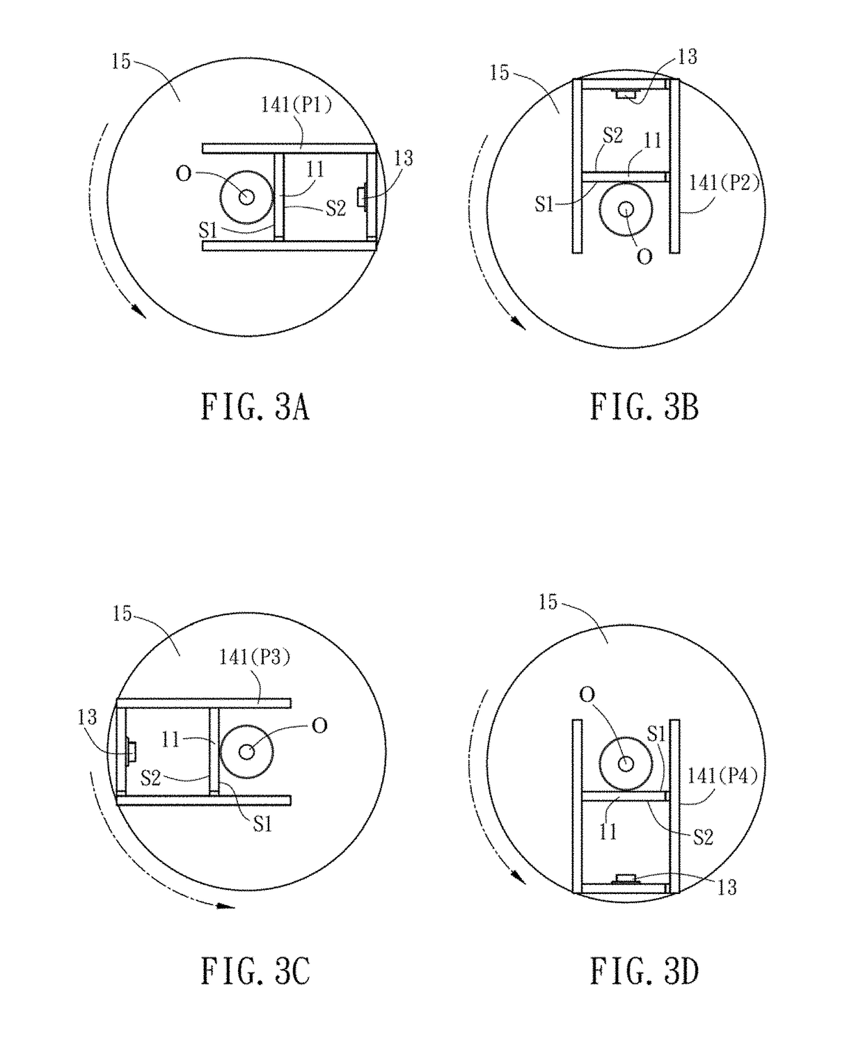
[0108]Different from the detecting apparatus 1a of the first embodiment, the holding unit 24 of the second embodiment includes a rotating bracket 242, and the screen 21 and the detecting unit 23 are fastened on the rotating bracket 242 for fixing the relative distance between the screen 21 and the detecting unit 23. By rotating the rotating bracket 242, the screen 21 and the detecting unit 23 can be moved with relative to the unmoved LED device O, so that the detecting unit 23 can capture different images of the second surface S2 of the screen 21 at different positions P1 and P5 as shown in FIGS. 3A to 3D.

[0109]In addition, the detecting apparatus 2 may further include a shell 26, which has a sector-like shape. The rotating bracket 242 is pivotally disposed on the shell 26, and the screen 21, the rotating bracket 242, the detecting unit 23 and the LED device O are all positioned inside...

third embodiment

[0111]FIG. 10 is a schematic diagram of a detecting apparatus 3 according to the invention.

[0112]Different from the detecting apparatus 1a of the first embodiment, the detecting unit 33 of the detecting apparatus 3 further includes a galvo mirror assembly 331 and a detecting device 332. The galvo mirror assembly 331 scans the image of every point of the second surface S2 of the screen 31 in sequence. In this case, the galvo mirror assembly 331 includes two optical galvo mirrors, and the detecting device 332 is a spectrometer for example. The two optical galvo mirrors are rotated relatively so as to scan the images of the second surface (not shown) of the screen 31 with different coordinates in sequence. In addition, the LED device O emits light to the screen 31, and the spectrometer receives the intensity of the light projected on different coordinates of the second surface. Moreover, since the LED device O is disposed on a rotating unit 35, it is possible to detect the light intens...


PUM


Abstract

A detecting apparatus for detecting an object includes at least a screen, at least a detecting unit and at least a holding unit. The screen is partial light-permeable and has a first surface and an opposite second surface. The object is disposed adjacent to the first surface of the screen. The detecting unit is disposed corresponding to the object and located adjacent to the second surface of the screen. The holding unit holds the relative distances between the screen, the object and the detecting unit. The detecting unit captures the image of the second surface of the screen so as to calculate the optical field distribution of the object. The detecting apparatus can measure the optical field distribution of an object quickly and has the advantages of low cost and high accuracy.

Description

CROSS REFERENCE TO RELATED APPLICATIONS[0001]This Non-provisional application claims priority under 35 U.S.C. § 119(a) on Patent Application No(s). 100138395 filed in Taiwan, Republic of China on Oct. 21, 2011, the entire contents of which are hereby incorporated by reference.BACKGROUND OF THE INVENTION[0002]Field of Invention[0003]The present invention relates to a detecting apparatus and a detecting method, and in particular, to a detecting apparatus and a detecting method for detecting optical field distribution.[0004]Related Art[0005]As the continuous improvements of manufacturing processes and materials, various kinds of light sources, such as LED (light-emitting diode), are developed recently. Due to the manufacturing processes, each light source or light source product has individual unique light intensity distribution, so that optical designer usually needs the optical field distribution thereof to proceed with the further precise design and optical simulation, thereby fabri...

Claims


Application Information

Patent Timeline
Patent Type & Authority Patents(United States)
IPC IPC(8): G01J1/04G01J1/02G01J1/42
CPCG01J1/0403G01J1/0266G01J1/0474G01J2001/4252G01J2001/4247
Inventor SUN, CHING-CHERNGYU, YEH-WEICHEN, YEN-LINCHEN, WEI-HSIN
Owner NAT CENT UNIV
Why Eureka
Try Eureka