Operating systems for an RFID tag
What is Al technical title?
Al technical title is built by PatSnap Al team. It summarizes the technical point description of the patent document.
a technology of rfid tags and operating systems, applied in the field of radio frequency identification (rfid) tags, can solve the problems of inability to interact with rfid tags, the information associated with assets, and the rfid tags being left alone, and achieving the effect of increasing ionizing radiation
Active Publication Date: 2018-04-24
TEGO INC
View PDF272 Cites 418 Cited by
Summary
Abstract
Description
Claims
Application Information
AI Technical Summary
This helps you quickly interpret patents by identifying the three key elements:
Problems solved by technology
Method used
Benefits of technology
[0015]In embodiments, the energy to power at least one of the first RF tag and the second RF tag may be from the RF device. The first RF tag may operate using energy received from the RF device and the second RF tag may operate using energy received from an RF signal from the first RF tag. The first RF tag and the second RF tag may receive the RF signal from the RF device, such as where the data transferred from the first RF tag to the second RF tag is transferred from the first RF tag, to the RF device, and then to the second RF tag. The data transferred may be transferred directly from the first RF tag to the second RF tag without being transmitted to the RF device. The transfer of data from the first RF tag to the second RF tag may be executed without data being transmitted from the RF device to either the first RF tag or the second RF tag. The RF device may be a third RF tag powered by an external energy source, such as where the external energy source is a battery, is solar energy, and the like. The system may further comprise a third RF tag adapted to operate using energy received from an RF signal, where the third RF tag is out of range of the RF signal from the RF device, and the data transferred from the first RF tag to the second RF tag is subsequently relayed from the second RF tag to the third RF tag, such as where the third RF tag operates using energy received from an RF signal from the second RF tag. The system may further comprise a third RF tag adapted to operate using energy received from an RF signal, where the first RF tag, the second RF tag, and the third RF tag are adapted to exchange data, such as where the exchange of data is through a network protocol; the exchange of data is executed from only data transferred between the first RF tag, the second RF tag, and the third RF tag; the exchange of data comprises transfer of data between the RF device and at least one of the first RF tag, the second RF tag, and the third RF tag; and the like. In embodiments, the RF device may be a forth RF tag that is powered by an external energy source, such as where the external energy source is a battery, solar energy, and the like. In embodiments, the first RF tag and the second RF tag may be operable through effects of environmental changes due to an increase in mechanical vibration, a change in temperature, a change in humidity, an increase in ionizing radiation, due to mechanical shock, and the like.
Problems solved by technology
Conventionally, standard software, whether office, business, enterprise or of other type, is not capable of interacting with RFID tags.
RFID tags have also been traditionally limited to small amounts of data (e.g., as asset ID related information) and non-standard interface software, leaving the RFID tag, and the information associated with its asset, isolated from general access—such as through the Internet.
Many such devices lack connected power sources, and it can be quite expensive to provide batteries or energy harvesting (e.g., solar cell) technologies.
Method used
Image
Click on the blue label to locate the original text in one second.
Reading with bidirectional positioning of images and text.
Examples
Embodiment Construction
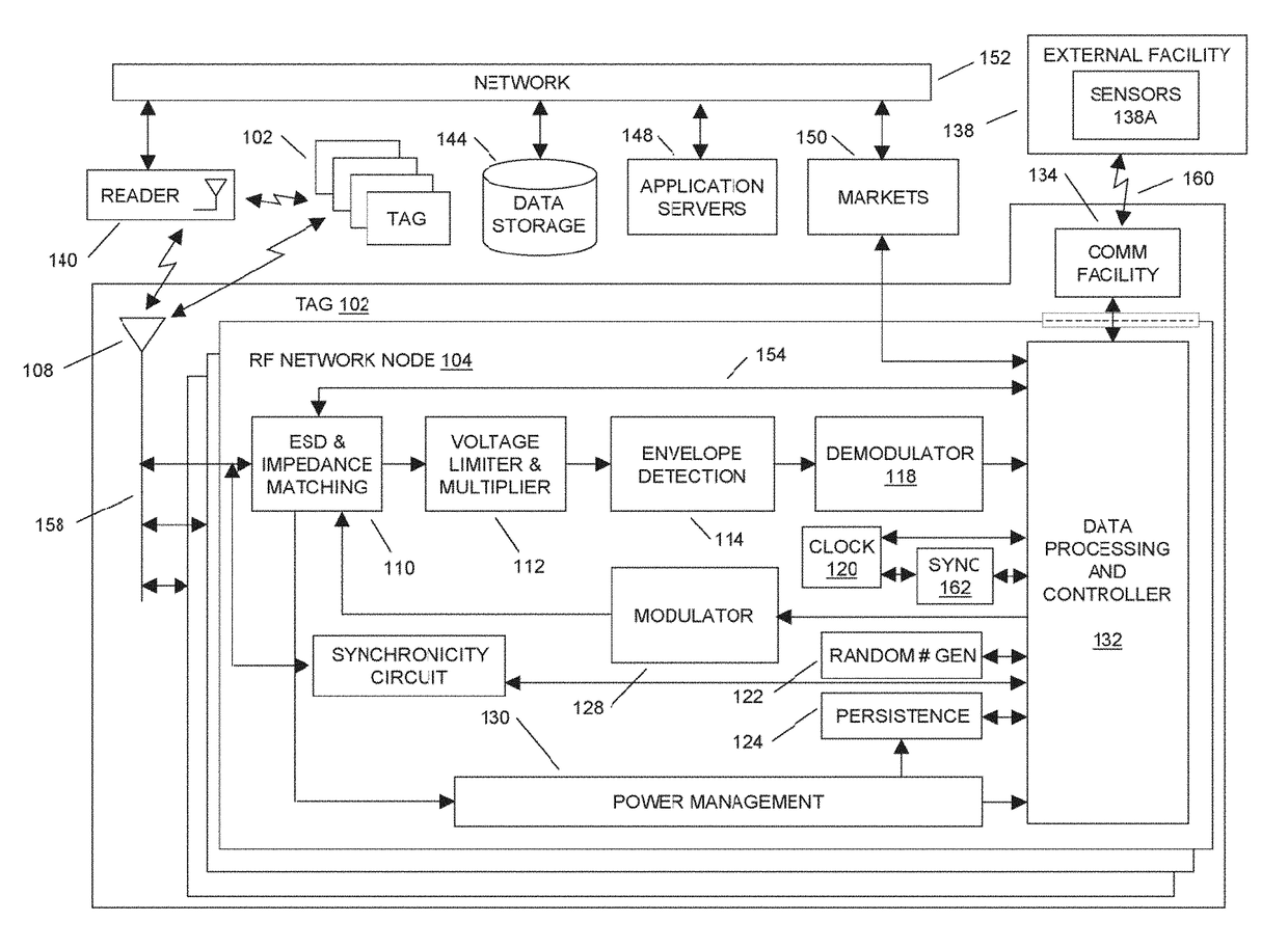
[0061]In aspects of the systems and methods described herein, although the term radio frequency identification (RFID) tag is used throughout the disclosure, the usage of this term is not meant to be limiting, such as to traditional RFID technologies (e.g., RFID technologies utilizing RFID protocols for interfacing with RFID tags, such as containing an identifier code for inventory tracking, and the like). The usage of the term RFID tag in the present disclosure pertains more generally to electronic devices communicating at least in part through wireless RF technology, including any near-field and / or far-field technologies and communication protocols known to the art.
[0062]In aspects of the systems and methods described herein, a radio frequency identification (RFID) tag may use multiple RF network nodes (e.g. radio microchips) to communicate information to a RFID reader, a network, other RFID network nodes, or the like. The communication of the information may be provided to the RFI...
PUM
Abstract
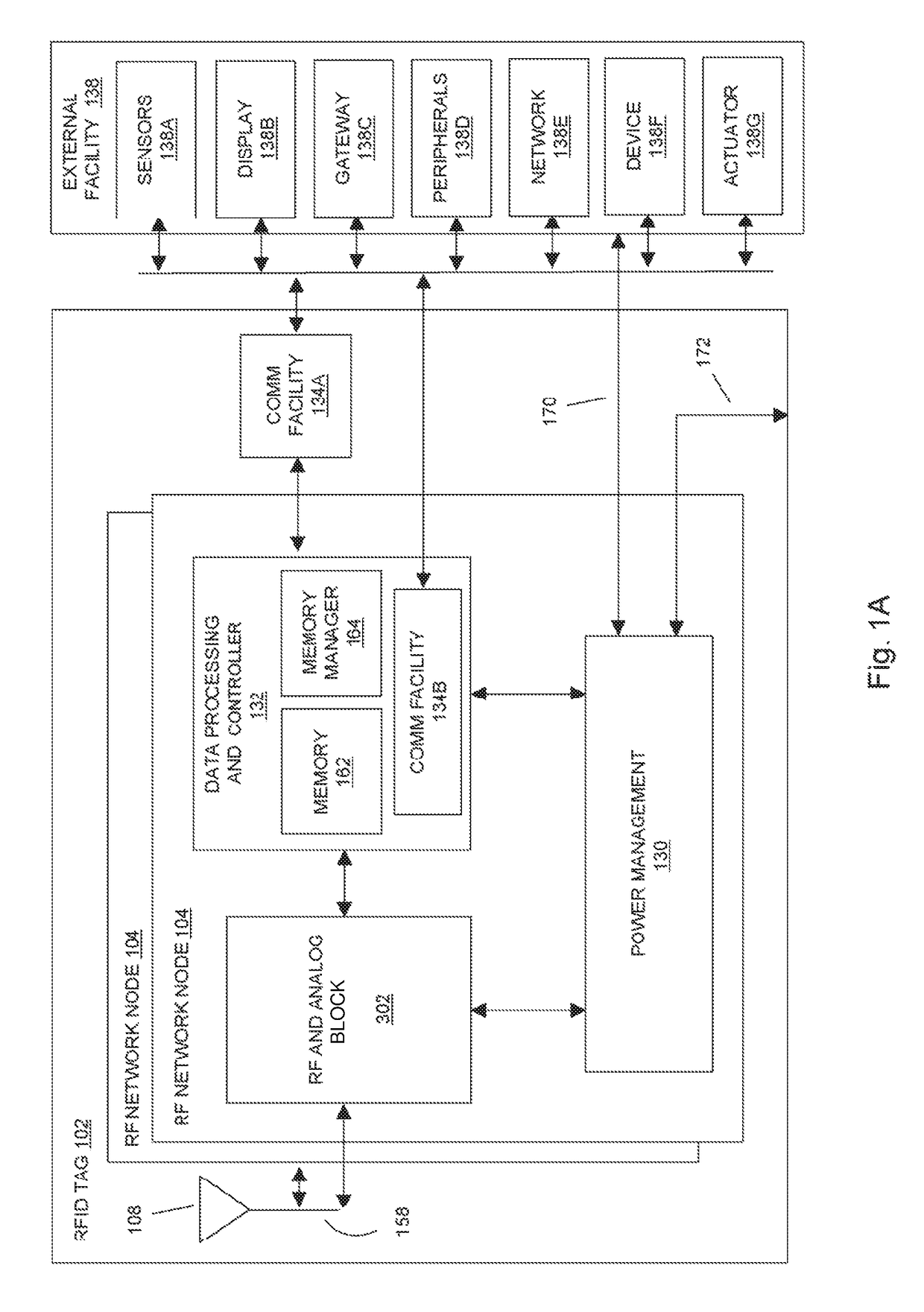
In embodiments of the present invention improved capabilities are described for a wireless computing device, comprising an antenna; an analog block for receiving and transmitting an RF signal through the antenna, wherein the energy from the received RF signal provides power to the wireless computing device; and a data processing and controller block for data management, wherein the data processing and controller block comprises: (i) a first program memory adapted to store a first set of instructions comprising a system call adapted to perform at least one function, and (ii) a second program memory adapted to store a second set of instructions comprising an instruction to call the system call, wherein the data processing and controller block is adapted to execute the first set of instructions and the second set of instructions,wherein the antenna, analog block, and data processing and controller block are mounted on a single substrate.
Description
CLAIM OF PRIORITY[0001]This patent application is a continuation of U.S. patent application Ser. No. 15 / 198,485, filed Jun. 30, 2016.[0002]U.S. patent application Ser. No. 15 / 198,485 is a continuation of U.S. patent application Ser. No. 14 / 870,731, Sep. 30, 2015, now U.S. Pat. No. 9,418,263.[0003]U.S. patent application Ser. No. 14 / 870,731 claims the benefit of the following provisional patent applications: U.S. Patent Application Ser. No. 62 / 057,277 filed Sep. 30, 2014 and U.S. Patent Application Ser. No. 62 / 063,588 filed Oct. 14, 2014.CROSS-REFERENCE TO RELATED APPLICATIONS[0004]This patent application is related to the following patent applications: U.S. patent application Ser. No. 11 / 609,277, filed Dec. 11, 2006; U.S. patent application Ser. No. 11 / 926,033, filed Oct. 28, 2007, now U.S. Pat. No. 8,279,065; U.S. patent application Ser. No. 12 / 393,863, filed Feb. 26, 2009, now U.S. Pat. No. 8,242,911; U.S. patent application Ser. No. 12 / 629,955, filed Dec. 3, 2009, now U.S. Pat. N...
Claims
Application Information
Patent Timeline
Application Date:The date an application was filed.
Publication Date:The date a patent or application was officially published.
First Publication Date:The earliest publication date of a patent with the same application number.
Issue Date:Publication date of the patent grant document.
PCT Entry Date:The Entry date of PCT National Phase.
Estimated Expiry Date:The statutory expiry date of a patent right according to the Patent Law, and it is the longest term of protection that the patent right can achieve without the termination of the patent right due to other reasons(Term extension factor has been taken into account ).
Invalid Date:Actual expiry date is based on effective date or publication date of legal transaction data of invalid patent.