
Energy storage system (ESS) using uninterruptible power supply (UPS)

a technology of energy storage system and power supply, which is applied in the directions of emergency power supply arrangement, liquid/fluent solid measurement, transportation and packaging, etc., can solve the problems of voltage irregularity, voltage distortion, and difficulty in verifying the effect of the high voltage connector band with respect to the entire power system, so as to reduce the cost of extending and purchasing and stably supply power to a load

Active Publication Date: 2018-04-24
LG CNS
View PDF23 Cites 0 Cited by
  • Summary
  • Abstract
  • Description
  • Claims
  • Application Information

AI Technical Summary

Benefits of technology

The present invention provides an energy storage system that can be built using an existing uninterruptible power supply (UPS), reducing the need for additional equipment and lowering costs. The system also includes a controller that monitors the battery array and adjusts its discharge to prevent it from becoming overused. The invention helps to extend the lifespan of the battery array and ensures a steady supply of power even in the event of a power outage or emergency situation. Overall, this invention provides a flexible and reliable solution for storing energy in a cost-effective and efficient way.

Problems solved by technology

In addition, the ESS is not considered at a stage of designing the construction of a building and thus, it is difficult to verify the effect of the high voltage connector band with respect to the entire power system.
In particular, voltage distortion may occur when driving the power equipment, for example, the PCS of the ESS.
In addition, a voltage may irregularly vary during a voltage stabilization period required when the PCS starts to supply power and suspends the power supply.
When the controller operates in the fault and repair mode, the controller may open the charge and discharge switch, and may supply the power through the uninterruptible power supply.

Method used


Image

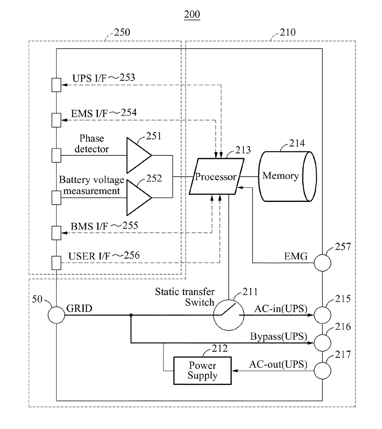
  • Energy storage system (ESS) using uninterruptible power supply (UPS)
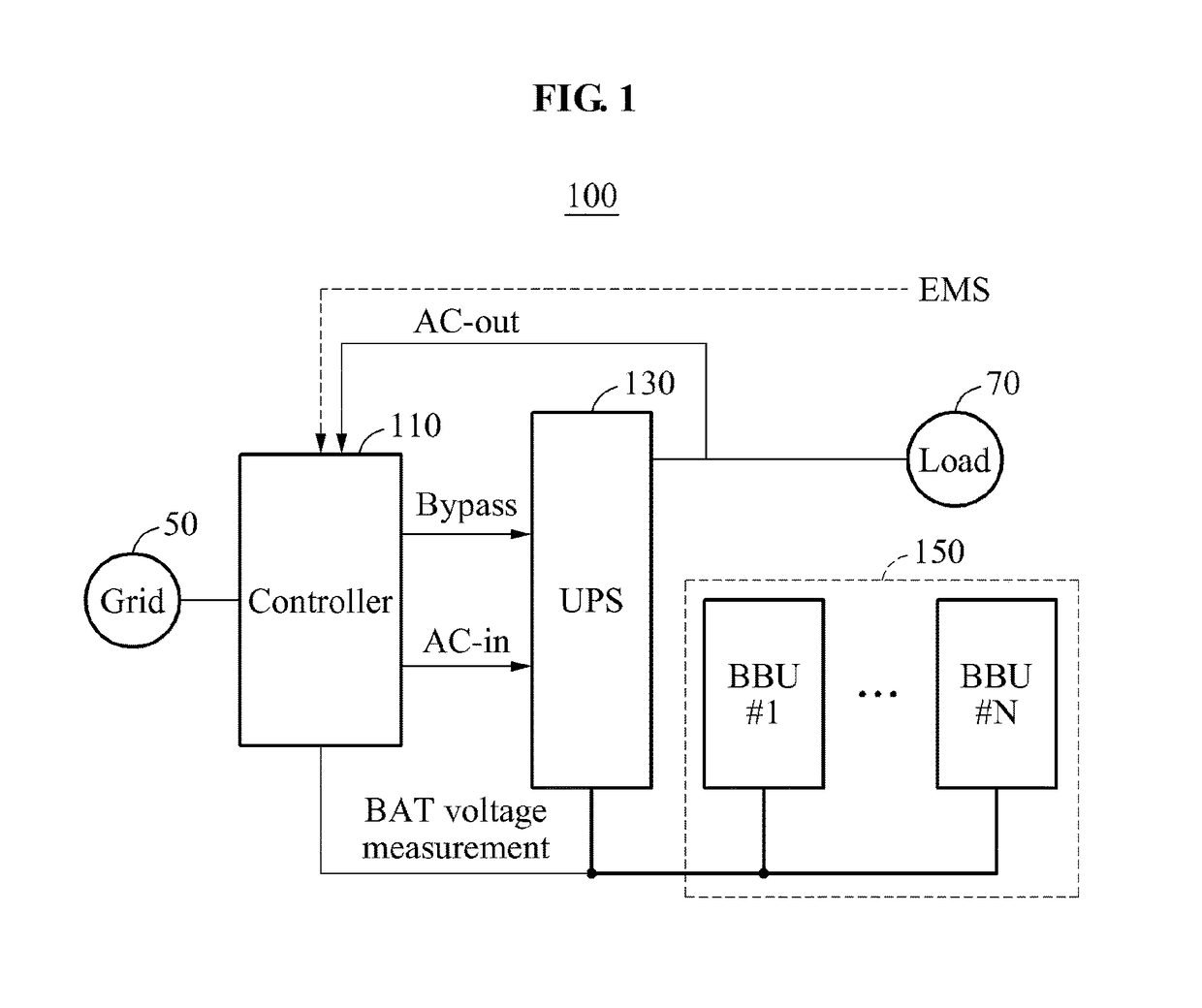
  • Energy storage system (ESS) using uninterruptible power supply (UPS)
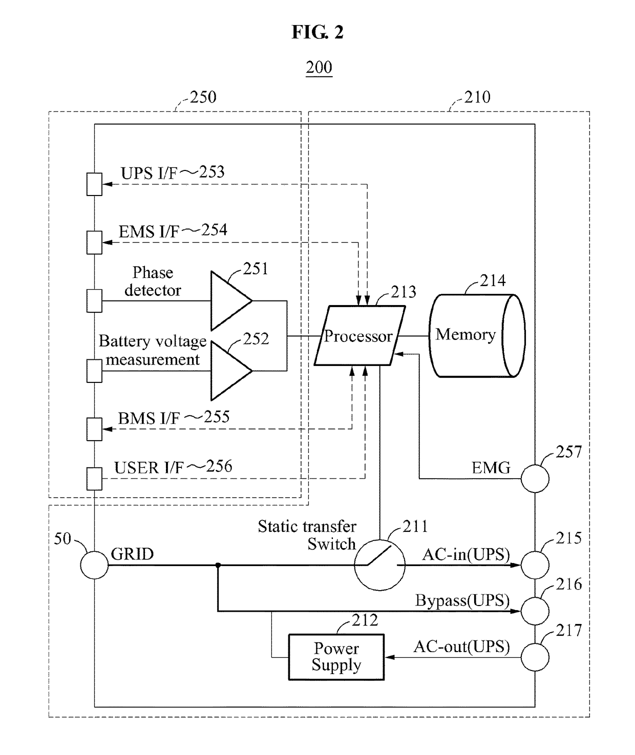
  • Energy storage system (ESS) using uninterruptible power supply (UPS)

Examples


Embodiment Construction

[0038]Hereinafter, embodiments will be described with reference to the accompanying drawings. Like reference numerals illustrated in the drawings refer to like constituent components.

[0039]Various alterations and modifications may be made to the embodiments. The embodiments are not construed as being limited to the disclosure and should be understood to include all changes, equivalents, and replacements within the idea and the technical scope of the disclosure.

[0040]Terms used herein are for the purpose of describing particular embodiments only and are not to be limiting of the embodiments. As used herein, the singular forms “a”, “an”, and “the” are intended to include the plural forms as well, unless the context clearly indicates otherwise. It will be further understood that the terms “include / comprise” and / or “have” when used in this specification, specify the presence of stated features, integers, steps, operations, elements, components, and / or combinations thereof, but do not pr...


PUM


Abstract

An energy storage system that includes an uninterruptible power supply configured to supply first power to a load and a battery array comprising a backup battery unit. The system further includes a controller to cut off the first power supplied by the uninterruptible power supply at a first time and control the uninterruptible power supply and the battery array to supply second power to the load using power stored in the battery array. Typically, the second power is supplied when the first power is cut off.

Description

CROSS-REFERENCE TO RELATED APPLICATIONS[0001]Pursuant to 35 U.S.C. § 119(a), this application claims the benefit of earlier filing date and right of priority to Korean Patent Application No. 10-2013-0155668, filed on Dec. 13, 2013, the contents of which are all hereby incorporated by reference herein in their entirety.BACKGROUND[0002]1. Field of the Invention[0003]Embodiments of the present invention relate to an energy storage system (ESS) using an uninterruptible power supply (UPS).[0004]2. Description of the Related Art[0005]An energy storage system (ESS) according to the related art includes a battery for the ESS and a power conditioning system (PCS), and connects to a high voltage, for example, 22.9 kV power line supplied from a grid. Here, a vacuum circuit breaker (VCB), a transformer (TR), and an air circuit breaker (ACB) are to be installed for high voltage connection.[0006]Although a high voltage connector band having a required capacity is already provided when configuring...

Claims


Application Information

Patent Timeline
Patent Type & Authority Patents(United States)
IPC IPC(8): H02J9/04H02J9/06G06F1/26H02J3/32H02J7/34
CPCH02J9/061H02J9/04Y10T307/625H02J7/00H02J9/06
Inventor YEON, IN CHOLKOO, BON JUNLEE, KWAN BOKLEE, KWANG HOJEONG, EUN KIJUNG, CHUNG HYUN
Owner LG CNS
Learn More