Protective structure for sporting equipment

a technology for protecting structures and sporting equipment, applied in the direction of racket sports, sports equipment, etc., can solve the problems of reducing the ability of the piece to effectively distribute shocks to a wider area, the raw material is easily impacted, and the thickness of the support ribs is optimized. , to achieve the effect of sufficient stiffness/strength, minimizing raw material wavyness, and optimizing the thickness of the support ribs

Active Publication Date: 2018-05-01
LICENSING OF FINLAND
View PDF14 Cites 1 Cited by
  • Summary
  • Abstract
  • Description
  • Claims
  • Application Information

AI Technical Summary

Benefits of technology

[0012]The support rib structure forms a cell like structure having a large open surface. The large open surface contributes in making the protective structure light. The support ribs can be dimensioned so that the width of the support ribs in the direction of the surface of the support structure is smaller than the height of the support ribs in the direction perpendicular to the surface of the support structure. With the height of the support ribs it is possible to regulate the stiffness of the protective structure in the direction perpendicular to the surface of the protective structure. The support ribs can on the other hand be kept narrow in the direction of the surface of the protective structure in order to achieve a large open area. A large open area makes the air permeability of the protective structure also especially high.
[0013]The protective structure can thus on the other hand be made light, but on the other hand stiff enough. The stiffness of the protective structure can be regulated also by changing the size of the inner frame. By using small inner frames a more stiff structure is achieved and by expanding the inner frames a more loose structure is achieved when the material thicknesses of the support ribs are kept the same.
[0014]The amount of material used in the support rib structure can be optimized in relation to the stiffness by varying the thickness of the support rib structure in a direction perpendicular to the surface formed by the support rib structure so that the material thickness is greater at the middle of the support rib structure compared to the thickness at the edges of the support rib structure. The material can be concentrated on those portions of the support rib structure where the benefit in relation to the stiffness is the greatest. By concentrating material more to the middle of the support structure the middle part of the support structure will become more stiff and the edges more loose. The middle part of the support structure does in this way receive effectively chocks and transfers chock energy to the edges of the support structure. The more loose edge parts of the support structure also contribute to the fitness of the support structure in sporting equipment, which improves the user comfort of the support structure.
[0017]When the protective structure is manufactured by injection molding the waist of raw material can be minimized compared to a protective structure manufactured by cut-dying. There is always a rather big waist when pieces of a desired size and form are die-cut from a uniform sheet with die-cut technique. Injection molding makes it is also possible to optimize the thickness of the support ribs so that a sufficient stiffness / strength is achieved with a minimum of material. Injection molding makes it possible to design the form of the support ribs and thus also the form of the whole protective structure in a desired way. The support rib structure can thus be designed esthetically in a desired way. Suitable materials for injection molding are all plastic materials as well as plastic materials into which other reinforcement materials such as e.g. carbon fiber have been mixed. The material must naturally be such that the material becomes hard enough after hardening. The protective structure can be manufactured from such a plastic grade or such a mixture of a plastic and a reinforcement material that are best suitable for each use.

Problems solved by technology

A protective structure made of sheet like material by die-cutting becomes fairly heavy.
The thickness of the material is the same throughout the whole piece and the ability of the piece to distribute shocks effectively to a wider area remains rather limited.

Method used


Image

  • Protective structure for sporting equipment
  • Protective structure for sporting equipment
  • Protective structure for sporting equipment

Examples


Embodiment Construction

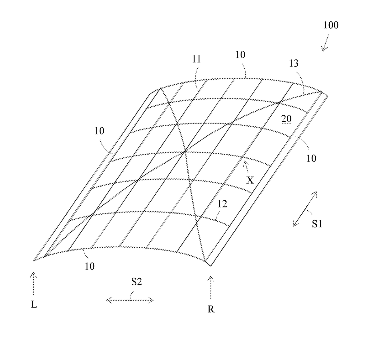
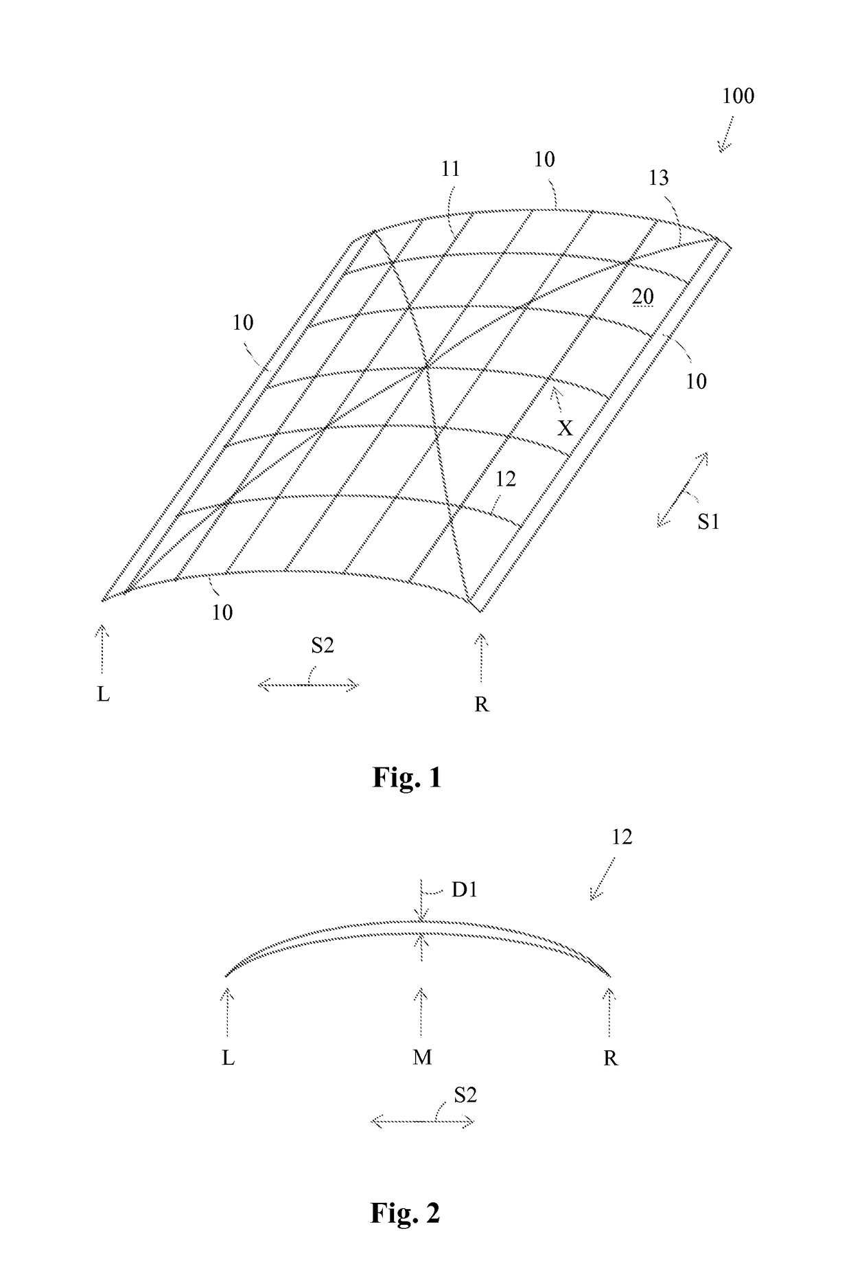
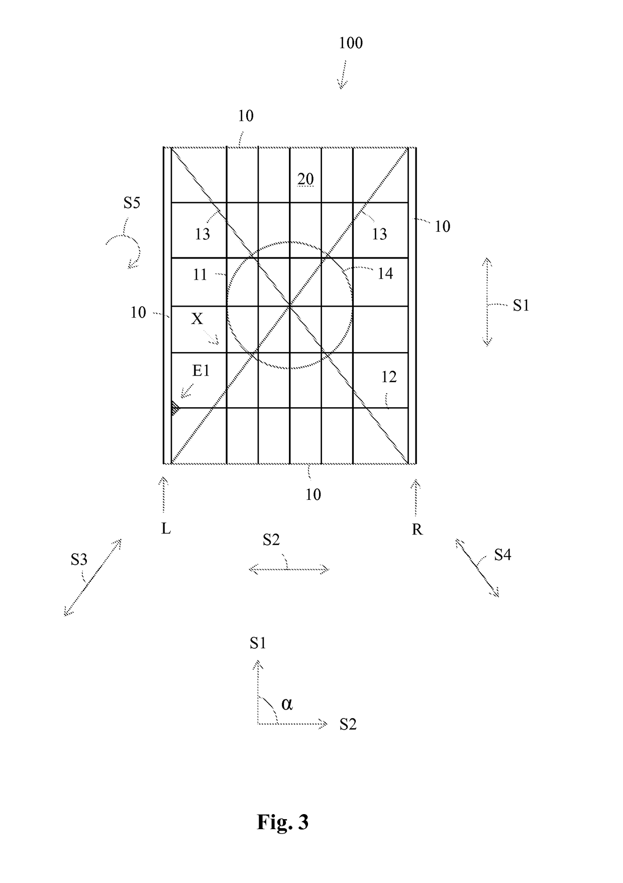
[0024]FIG. 1 presents an axonometric figure of a protective structure according to the invention. The protective structure comprises a curved, mesh like or cell like support rib structure 100. The support rib structure 100 is formed of support ribs 11 extending in a first direction S1 i.e. in a length direction and of crossing support ribs 12 extending in a second direction i.e. in a traverse direction. The outermost support ribs 11, 12 in each direction S1, S2 form an outer frame 10 of the support rib structure 100. Inner frames 20 are formed between the crossing points X of the support ribs 11, 12. The support rib structure 100 comprises further crossing support ribs 13 extending in a third direction S3 and in a fourth direction S4. The support ribs 11 extending in the longitudinal direction S1 are straight. The support ribs 12 extending in the traverse direction S2 and the crossing support ribs 13 are curved. The longitudinal S1 support ribs 11 at each outer edge L, R of the supp...


PUM

PropertyMeasurementUnit
angleaaaaaaaaaa
thicknessaaaaaaaaaa
surface areaaaaaaaaaaa

Abstract

The protective structure comprises a at least in one direction curved support rib structure of a material or a material composition that is suited for injection molding, which support rib structure is formed of an outer frame and of inner frames fitted into the interior space of the outer frame and being fixed to each other and / or to the outer frame. The material thickness of the support rib structure varies in a direction perpendicular to a surface formed by the support rib structure so that the material thickness is greater at the middle of the support rib structure compared to the material thickness at the edges of the support rib structure.

Description

RELATED APPLICATION INFORMATION[0001]This application is a 371 of International Application PCT / FI2013 / 051168 filed 16 Dec. 2013, which claims priority from Finnish Application No.: 20126377 filed 27 Dec. 2012, the content of which is incorporated herein by reference.TECHNICAL FIELD[0002]The invention is directed to a protective structure for sporting equipment according to the preamble of claim 1.[0003]The invention is also directed to a method for producing a protective structure for sporting equipment according to the preamble of claim 11.[0004]Sporting equipment such as protective equipment for ice hockey, football etc. comprises protective structures. Protective structures are present e.g. in ice hockey leg shields, breast and shoulder shields and in pants. The protective structures are fairly stiff structures usually made of plastic material, the purpose of the protective structures being to receive shocks and to distribute the energy of the shock to a wider area.BACKGROUND AR...

Claims


Application Information

Patent Timeline
Patent Type & Authority Patents(United States)
IPC IPC(8): B32B3/12A41D13/015A41D13/05B32B3/30A63B71/12A63B102/24
CPCA63B71/12A41D13/015A41D13/05A63B71/1225A41D13/0506A63B2243/0025A63B2071/1233A63B2071/1241A63B2071/1258A63B2102/24A63B2209/02A41D13/0543A41D31/0005A63B71/08
Inventor NYLUND, MAURI
Owner LICENSING OF FINLAND
Why Eureka
Try Eureka