
System and method for measuring a resonance frequency of a tube

a technology of resonance frequency and measurement method, which is applied in the field of system and method of measuring resonance frequency of tubes, can solve the problems of limited resonance frequency determined by fot or ios, difficult to determine resonance frequency for the arteries, and use for clinical practice, and achieve the effect of accurately measuring the resonance frequency of the tub

Active Publication Date: 2018-05-01
KONINK PHILIPS ELECTRONICS NV
View PDF18 Cites 0 Cited by
  • Summary
  • Abstract
  • Description
  • Claims
  • Application Information

AI Technical Summary

Benefits of technology

[0015]The advantage is that the system can more accurately measure a resonance frequency of a tube.
[0017]The advantage is that a more accurate property / a set of more accurate properties of a tube can be measured based on the accurate resonance frequency.
[0019]The advantage is that a more accurate property / a set of more accurate properties of a tube can be calculated based on the accurate resonance frequency.
[0021]The advantage is that a cough can be realized more effectively based on the accurate resonance frequency.
[0026]The advantage is that the system can more accurately generate a graph to show at least one resonance frequency of a tube.

Problems solved by technology

However, the current method is not useful for clinical practice, since the arteries are in the human body or animal body, so in normal clinical practice, people cannot see whether the arteries are resonant, which makes it difficult to determine a resonance frequency for the arteries based on the current method.
However, the resonance frequency determined by FOT or IOS is limited to low frequencies due to the inherent inaccuracy of the system.
Especially, some diseases only have an impact on part of the whole lung system.
But, currently, based on FOT or IOS, it is difficult to distinguish resonances of the small bronchioles, the main bronchi, and trachea of a lung system separately.

Method used


Image

  • System and method for measuring a resonance frequency of a tube
  • System and method for measuring a resonance frequency of a tube
  • System and method for measuring a resonance frequency of a tube

Examples


Embodiment Construction

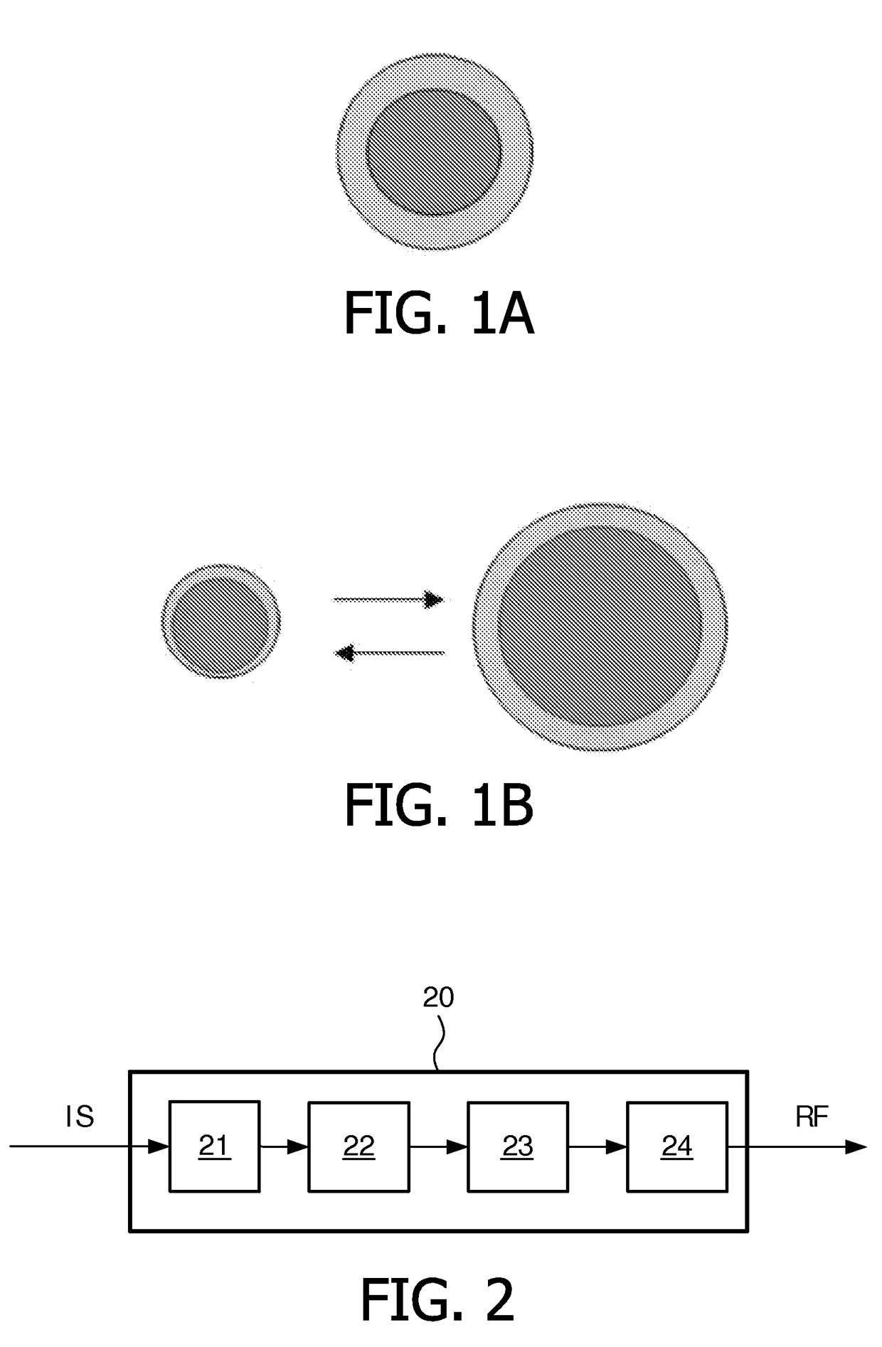
[0039]A velocity of transmitting a pressure pulse in a tube correlates to the properties of the tube wall, the properties of the content (e.g. gas / liquid) in the tube, the diameter of the tube, and an external oscillation pressure which causes a variation of the diameter of the tube.

[0040]For example, the velocity of transmitting a pressure pulse in a blood vessel correlates to the compliance of the blood vessel wall, the density of blood in the blood vessel, the diameter of the blood vessel, and an external oscillation pressure. An external oscillation pressure causes the blood vessel wall to vibrate with positive divergence and negative divergence, so as to cause the diameter of the blood vessel to increase and decrease in a cyclic pattern. A velocity variation of a pressure pulse in the blood vessel happens based on the diameter variation of the blood vessel. The velocity variation of a pressure pulse in a blood vessel causes a time variation of transmitting a pressure pulse from...


PUM


Abstract

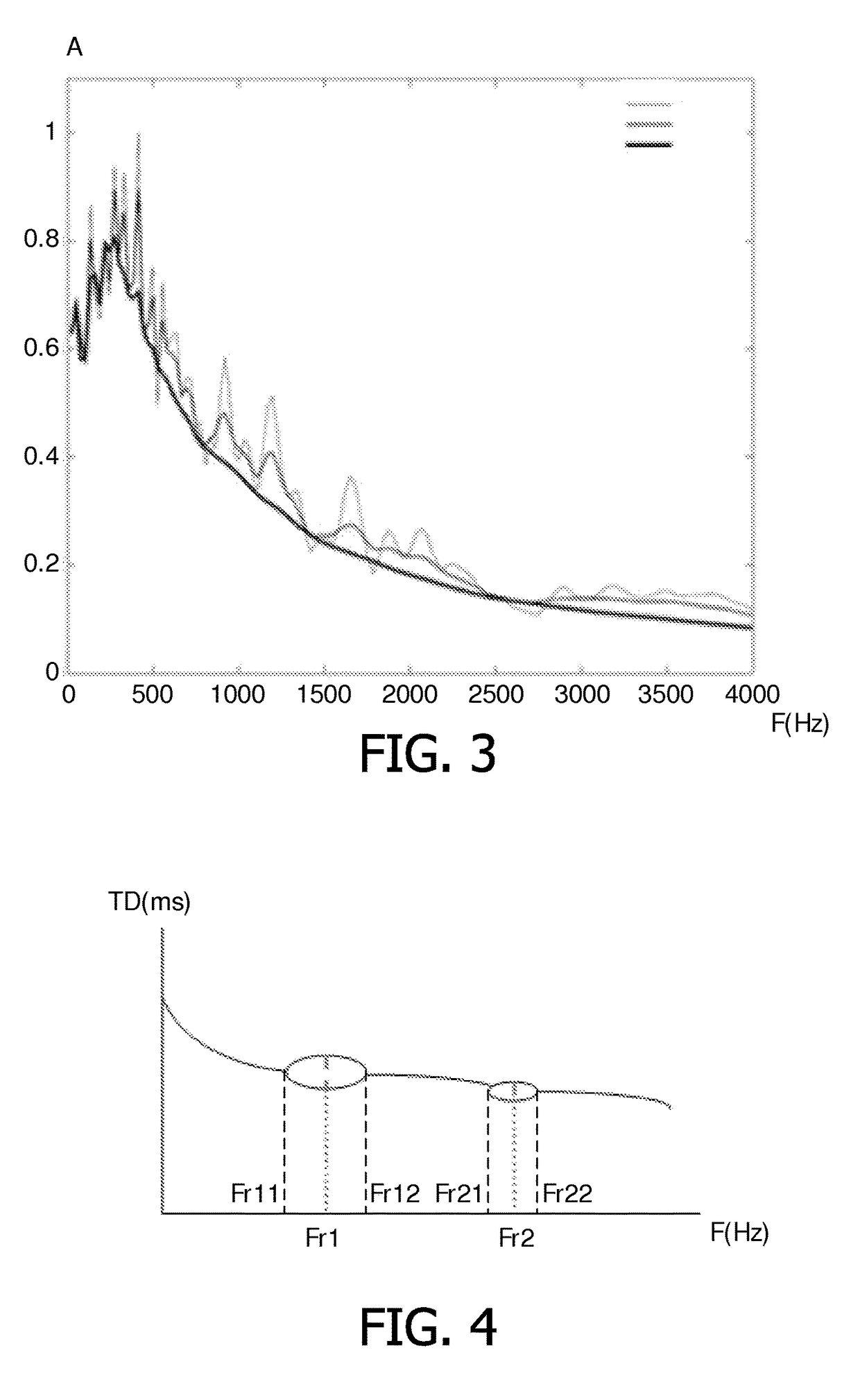
The invention proposes a system for measuring a resonance frequency of a tube. The system comprises: an oscillating unit (21) for oscillating the tube at a plurality of oscillation frequencies, respectively; a detecting unit (22) for detecting a time delay of transmitting a pressure pulse from a first position to a second position in the tube when the tube is oscillated at each oscillation frequency, wherein, when the tube is oscillated at each oscillation frequency in a specific oscillation frequency range of the plurality of oscillation frequencies, the detecting unit (22) detects a variation of the time delay—a determining unit (23) for determining a maximal variation of the time delay when the tube is oscillated at the oscillation frequencies in the specific oscillation frequency range; and—an indicating unit (24) for indicating an oscillation frequency corresponding to the maximal variation of the time delay, being a resonance frequency of the tube.

Description

FIELD OF THE INVENTION[0001]The invention relates to a system for, and method of, measuring properties of a tube, particularly to a system for, and method of, measuring a resonance frequency of a tube.BACKGROUND OF THE INVENTION[0002]In a human body or an animal body, the most notable flexible tubes are blood vessels and airways. The airways may comprise trachea, main bronchi, small bronchiole, etc. In the medical diagnostic area, it is useful to know the response of a tube to an excitation. The excitation can be a natural excitation, such as a contraction of a heart, or an artificial excitation. The artificial excitation can be a pressure excitation from an external body. The response of a tube to an excitation can be used for diagnosis of pathologies or used for optimizing therapeutic treatment.[0003]The response of a tube to an excitation can result in resonance. Resonance occurs when an external excitation leads to maximum energy storage in a tube and causes the maximal amplitud...

Claims


Application Information

Patent Timeline
Patent Type & Authority Patents(United States)
IPC IPC(8): G01H13/00A61B5/08A61B5/021A61B5/02A61B8/00A61B8/08
CPCG01H13/00A61B5/02007A61B5/08A61B8/00A61B5/02133A61B8/0891
Inventor BRAND, MAARTEN LEONARDUS CHRISTIANDONG, LIANGDU, JUAN
Owner KONINK PHILIPS ELECTRONICS NV
Learn More