Solenoid drive device

a solenoid drive and drive device technology, applied in the direction of relays, machines/engines, electric control, etc., can solve the problems of deteriorating the voltage accuracy of the constant voltage diode, and increasing the rated power of the solenoid, so as to reduce the resistance value and the rated power of the respective resistor. , to achieve the effect of preventing the deterioration of the capacitor

Active Publication Date: 2018-05-08
HITACHI ASTEMO LTD
View PDF6 Cites 0 Cited by
  • Summary
  • Abstract
  • Description
  • Claims
  • Application Information

AI Technical Summary

Benefits of technology

[0008]The present invention has been devised while taking into consideration the aforementioned problems, and has the object of providing a solenoid drive device that is capable of suppressing a variance in the value of the boost voltage due to heat.
[0012]Thus, according to the present invention, the boost voltage comparing unit that compares the value of the boost voltage with the predetermined voltage value, and the boost voltage discharge unit are disposed separately from one another. Consequently, the influence of heat on the boost voltage comparing unit from the boost voltage discharge unit is suppressed, and the process to determine the value of the boost voltage in the boost voltage comparing unit can be carried out with high accuracy.
[0013]As a result, with the present invention, it is possible to suppress a variance in the value of the boost voltage caused by heat. Further, a layout of the circuit configuration is made possible so as to suppress the influence of heat on the boost voltage comparing unit.
[0016]Thus, in the present invention, the boost voltage discharge unit further comprises a switching unit configured to be switched ON or OFF based on a judgment result of the boost voltage comparing unit, and a current limiting resistance device configured to limit a discharge current that flows in the boost voltage power source unit when the switching unit is switched ON. Since the value of the discharge current is suppressed by the current limiting resistance device, and the waveform of the discharge current is prevented from becoming steep, deterioration of the capacitor can effectively be prevented.
[0017]Further, if the current limiting resistance device is constituted by being divided into a plurality of resistors, it is possible for the power consumed by the current limiting resistance device to be divided among the respective resistors. By this feature, the resistance value and the rated power of the respective resistors can be reduced.

Problems solved by technology

However, when such a constant voltage diode is used, the constant voltage diode itself produces heat during limiting of the boost voltage.
Consequently, the voltage accuracy of the constant voltage diode deteriorates when the value of the boost voltage is limited.
As a result, the value of the boost voltage applied to the solenoid tends to vary, and there is a possibility for a variance to occur in the fuel injection amount that is injected into the interior of the cylinder from the injector.

Method used


Image

  • Solenoid drive device
  • Solenoid drive device
  • Solenoid drive device

Examples


Embodiment Construction

[0024]A preferred embodiment of a solenoid drive device according to the present invention will be described in detail below with reference to the accompanying drawings.

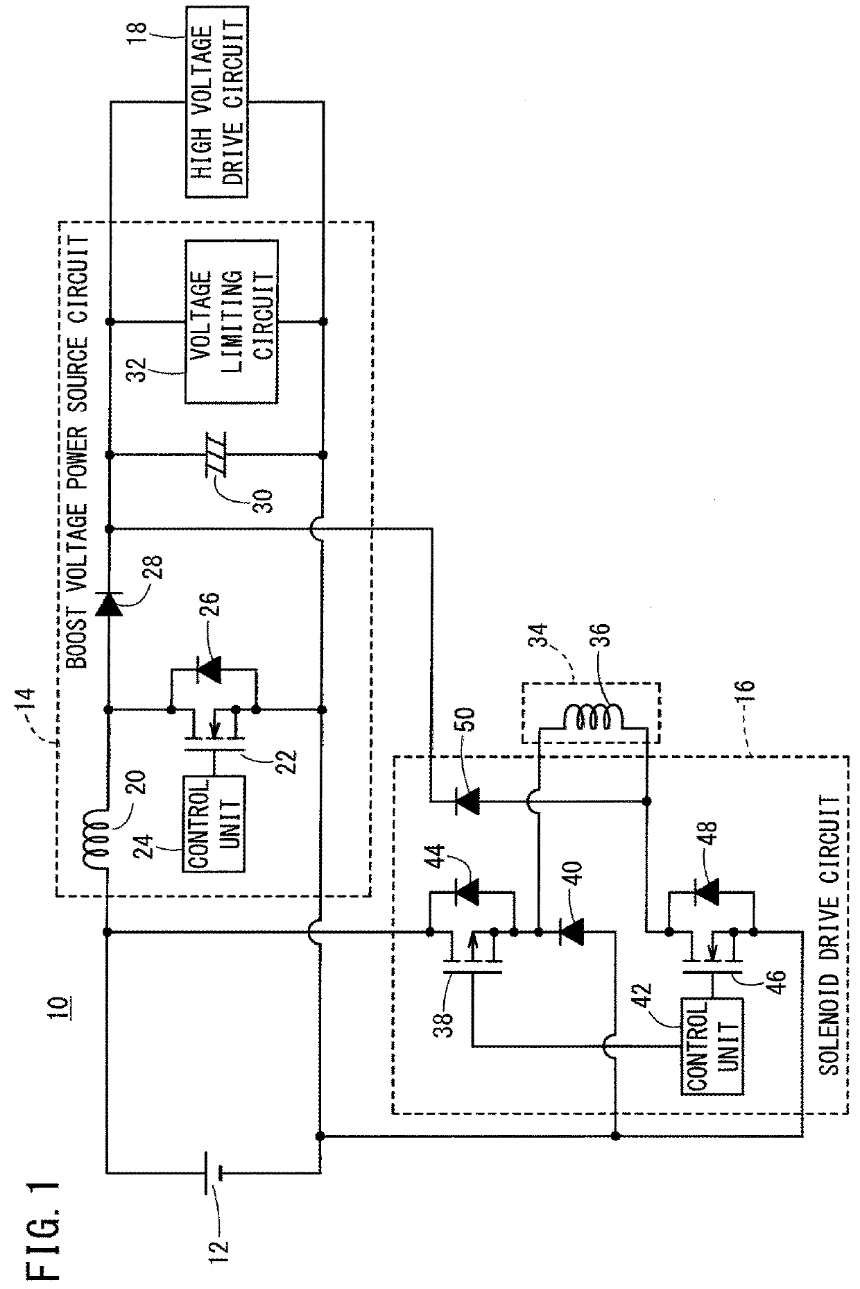
[0025]As shown in FIG. 1, a solenoid drive device 10 according to the present embodiment can be applied, for example, to a drive control device for a direct injection type of injector that injects fuel directly into the cylinder of an engine, and a drive control device for a fuel pump that supplies fuel to the aforementioned injector. More specifically, the solenoid drive device 10 includes a boost voltage power source circuit (boost voltage power source unit) 14 and a solenoid drive circuit (solenoid drive unit) 16, which are connected in parallel with respect to a battery 12 of a vehicle.

[0026]The boost voltage power source circuit 14 generates a high voltage (boost voltage) by boosting the power source voltage of the battery 12, and operates a high voltage drive circuit 18 by supplying the generated boost voltage ...


PUM

PropertyMeasurementUnit
boost voltageaaaaaaaaaa
regenerative energyaaaaaaaaaa
voltageaaaaaaaaaa

Abstract

A voltage limiting circuit of a solenoid drive device includes a function to limit the value of a boost voltage generated by a boost voltage power source circuit. The voltage limiting circuit is equipped with a boost voltage comparing unit and a boost voltage discharge unit. The boost voltage comparing unit compares a voltage-divided value of the boost voltage with a reference voltage value, and in the case that the voltage-divided value is higher than the reference voltage value, the boost voltage discharge unit lowers the voltage-divided value to be less than or equal to the reference voltage value.

Description

CROSS-REFERENCE TO RELATED APPLICATION[0001]This application is based upon and claims the benefit of priority from Japanese Patent Application No. 2015-025914 filed on Feb. 13, 2015, the contents of which are incorporated herein by reference.BACKGROUND OF THE INVENTION[0002]Field of the Invention[0003]The present invention relates to a solenoid drive device which drives a solenoid that acts as an inductance load.[0004]Description of the Related Art[0005]With a fuel injection device (injector) that injects fuel directly into the interior of a cylinder of an engine, a valve-open state of the injector is brought about by imposing a high voltage on a solenoid, which acts as an inductance load, and causing a large electric current to flow therein, and thereafter, the valve-open state is maintained by having a small holding electric current flow to the solenoid. In this case, a power source voltage is boosted and a high voltage (boost voltage) is generated by a boost voltage power source ...

Claims


Application Information

Patent Timeline
Patent Type & Authority Patents(United States)
IPC IPC(8): H01H47/00H01F7/06F02D41/20
CPCH01F7/064F02D41/20F02D2041/2048F02D2041/2013F02D2041/2003F02M51/06
Inventor WAKAI, MOTOSHIKIMURA, MASAYA
Owner HITACHI ASTEMO LTD
Why Eureka
Try Eureka