
System and method for through-the-wall-radar-imaging using total-variation denoising

a technology of total variation and denoising, applied in the field of denoising images, can solve problems such as noise reconstructed images, and achieve the effect of improving denoising

Active Publication Date: 2018-05-15
MITSUBISHI ELECTRIC RES LAB INC
View PDF5 Cites 0 Cited by
  • Summary
  • Abstract
  • Description
  • Claims
  • Application Information

AI Technical Summary

Benefits of technology

[0008]One embodiment of the invention incorporates spatial correlation of extended object reflections for object detection based on multipath elimination by a sparse inversion (MESI) method, which models denoising as a structured blind deconvolution problem with sparsity constraints on the scene and multipath reflections. This improves the denoising by ensuring that a separate convolution kernel is determined for each detected object to match the corresponding multipath reflections.

Problems solved by technology

However, depending on the dielectric permittivity and permeability of the walls, the echoes are often corrupted by indirect secondary reflections from the walls, which result in ghost artifacts that cause a noisy reconstructed image.

Method used


Image

  • System and method for through-the-wall-radar-imaging using total-variation denoising
  • System and method for through-the-wall-radar-imaging using total-variation denoising
  • System and method for through-the-wall-radar-imaging using total-variation denoising

Examples


Embodiment Construction

System Setup

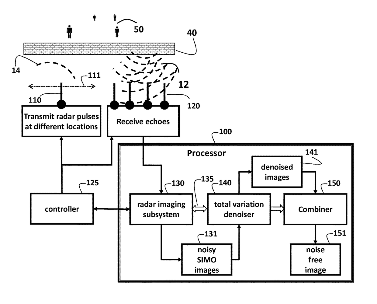
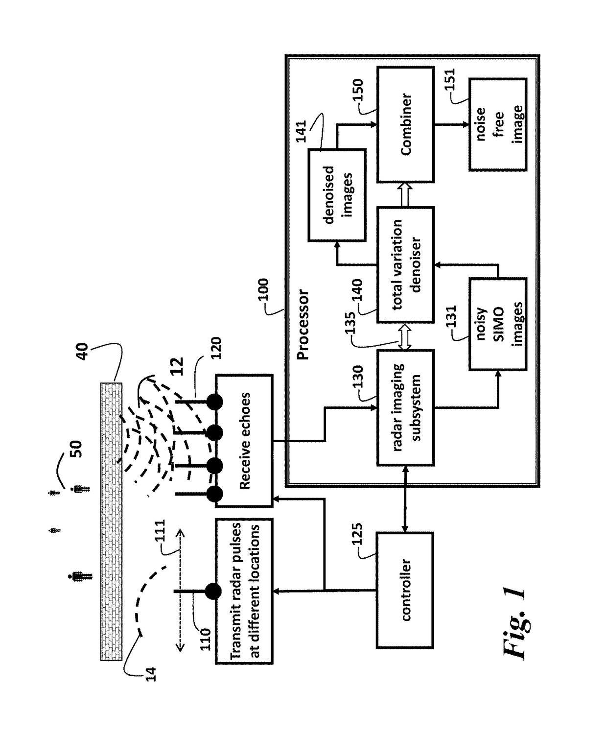
[0012]As shown in FIG. 1, the embodiments of our invention describe a system and method for determining a noise free image of a scene located behind a wall 40. Typically, the scene includes reflectors, such as objects, e.g., people 50. Details of the system setup, the scene and the effect of the wall are described in the related application, U.S. Publication No. 20150022390, “Method and System for Through-the-Wall Imaging using Sparse Inversion for Blind Multi-Path Elimination,” Mansour, Jul. 22, 2013, incorporated herein by reference.

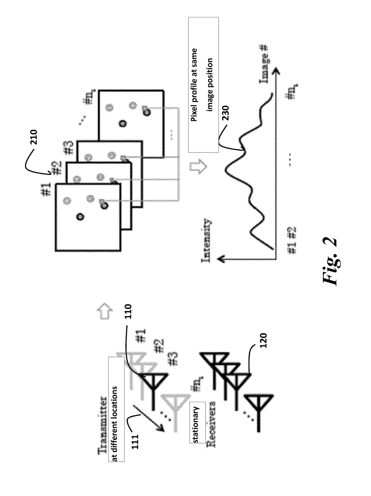
[0013]The system includes a transmit antenna 110 that emits a radar pulse 14 from different locations 111 in front of the wall 40. The radar pulses propagate through the wall and are reflected as echoes 12. Typically, the reflectors are objects 50, such as people. However, it is understood that invention can be applied to any type of behind the wall scene. A set of stationary receive antennas 120 acquire the echoes 12 that corresponding to ...


PUM


Abstract

A system and method determines a noise free image of a scene located behind a wall. A transmit antenna emits a radar pulse from different locations in front of the wall, wherein the radar pulses propagate through the wall and are reflected by the scene as echoes. A set of stationary receive antennas acquire the echoes corresponding to each pulse transmitted from each different location. A radar imaging subsystem connected to the transmit antenna and the set of receive antennas determines a noisy image of the scene for each location of the transmit antenna. A total variation denoiser denoises each noisy image to produce a corresponding denoised image. A combiner combines incoherently the denoised images to produce the noise free image.

Description

RELATED APPLICATION[0001]This application is a Continuation-in-Part application of U.S. Patent Publication No. 20150022390, “Method and System for Through-the-Wall Imaging using Sparse Inversion for Blind Multi-Path Elimination,” Mansour, Jul. 22, 2013, incorporated herein by reference. That application describes a method for detecting a target in a scene behind a wall based on multi-path elimination by sparse inversion (MESI).FIELD OF THE INVENTION[0002]This invention relates generally to through-the-wall imaging (TWI), and more particularly to denoising images using MIMO antenna arrays and compressive sensing to reconstruct a scene behind a wall.BACKGROUND OF THE INVENTION[0003]Through-the-wall-imaging (TWI) can be used to detect objects in a scene behind a wall. That is, the objects are positioned inside a structure enclosed by walls are detected from outside the structure. In a typical application, one or more transmit antennas emit radar pulses. The radar pulses propagate throu...

Claims


Application Information

Patent Timeline
Patent Type & Authority Patents(United States)
IPC IPC(8): G01S13/89G01S7/292G01S3/74G01S13/88G01S13/00
CPCG01S13/89G01S7/292G01S13/888G01S13/003G01S3/74
Inventor HANDA, HIROYUKIMANSOUR, HASSANLIU, DEHONGKAMILOV, ULUGBEK
Owner MITSUBISHI ELECTRIC RES LAB INC
Learn More