Fault enhancement method, fault development interpretation method, storage medium and electronic equipment

A technology for developing directions and faults, applied in the field of oil and gas exploration, it can solve the problems of small fault enhancement effect, large amount of calculation, difficulty in overcoming fault continuity, etc., to improve the signal-to-noise ratio and imaging quality, clear resolution, enhanced The effect of fault continuity

Pending Publication Date: 2022-03-04
CHINA PETROLEUM & CHEM CORP +1
View PDF0 Cites 0 Cited by
  • Summary
  • Abstract
  • Description
  • Claims
  • Application Information

AI Technical Summary

Problems solved by technology

[0006] The object of the present invention is: to solve the above problems, the present invention provides an optimized tomographic enhancement processing method, device, storage medium and electronic equipment, by adding optimization processing steps based on tomographic enhancement technology, and optimizing based on tomographic enhancement Processing, the variance operation and ant tracking operation are performed on the fault enhancement body obtained after the fault enhancement processing, which solves the problem of large calculation load in the fault enhancement method of seismic data with poor quality and weak fault information in the prior art , The enhancement effect of small faults is not obvious and it is difficult to overcome the problem of poor fault continuity, so as to improve the signal-to-noise ratio and imaging quality of seismic data, further clearly describe faults, and facilitate subsequent fault identification and extraction

Method used


Image

  • Fault enhancement method, fault development interpretation method, storage medium and electronic equipment
  • Fault enhancement method, fault development interpretation method, storage medium and electronic equipment
  • Fault enhancement method, fault development interpretation method, storage medium and electronic equipment

Examples


Embodiment 1

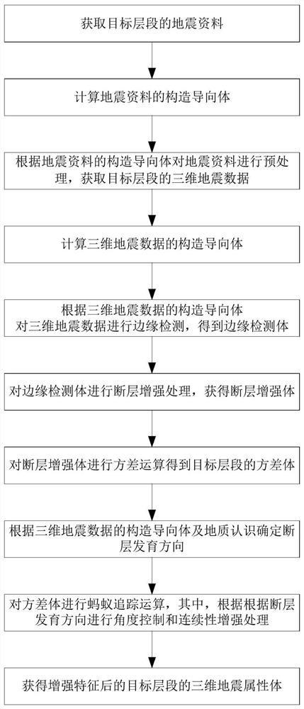
[0055] see Figure 1 to Figure 8 , this embodiment provides a tomographic enhancement method applicable to electronic equipment. When the method is applied to the electronic equipment, steps 101 to 103 are performed:

[0056] Step 101: Acquiring 3D seismic data of the target interval;

[0057] Step 101.1: Obtain seismic data of the target interval;

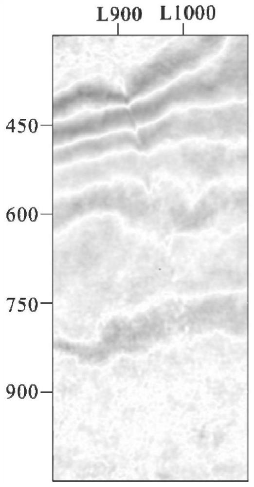
[0058] In this embodiment, taking the actual seismic data in a certain area as an example, the seismic data including the target interval are obtained, such as figure 2 Shown is the time slice map of the seismic data, the seismic data is the original seismic data, from figure 2 It can be seen that the fault information in the original seismic data is weak, the fault characteristics are not obvious, and contain more random noise, which brings great troubles to the detection and identification of faults. Among them, faults refer to the rock formations inside the crust Or the planar failure or planar rheological zone produced by...

Embodiment 2

[0091] see Figure 2 to Figure 10 On the basis of Embodiment 1, this embodiment further provides a fault development interpretation method applicable to electronic equipment. When the method is applied to the electronic equipment, steps 201 to 204 are performed:

[0092] Step 201: Acquiring 3D seismic data of the target interval;

[0093] Step 201.1: Obtain seismic data of the target interval;

[0094] In this embodiment, the actual seismic data in a certain area is still taken as an example, and the seismic data including the target interval are obtained, such as figure 2 Shown is the time slice map of the seismic data, the seismic data is the original seismic data, from figure 2 It can be seen that the fault information in the original seismic data is weak, the fault characteristics are not obvious, and contain more random noise, which brings great troubles to the detection and identification of faults;

[0095] Step 201.2: calculating the structural guide of the seismi...

Embodiment 3

[0129] This embodiment provides a computer-readable storage medium on the basis of Embodiment 2, such as flash memory, hard disk, multimedia card, card-type memory (for example, SD or DX memory, etc.), random access memory (RAM), static random access memory Access memory (SRAM), read-only memory (ROM), electrically erasable programmable read-only memory (EEPROM), programmable read-only memory (PROM), magnetic memory, magnetic disk, optical disk, server, App application store, etc., A computer program is stored thereon, and when the computer program is executed by the processor, the following method steps can be realized:

[0130] Step 301: Acquiring 3D seismic data of the target interval;

[0131] Step 301.1: Obtain seismic data of the target interval;

[0132] Step 301.2: Calculating the structural guide of the seismic data;

[0133] Specifically, analyze the amplitude and waveform information of the seismic data by scanning time windows, and establish a structural guide ch...


PUM


Abstract

The invention relates to the technical field of oil-gas exploration, in particular to a fault enhancement method, a fault development interpretation method, a storage medium and electronic equipment. The problems that in the prior art, a method for conducting fault enhancement on seismic data with poor quality and weak fault information is large in calculated amount, the enhancement effect of small faults is not obvious, and poor fault continuity is difficult to overcome are solved. The method comprises the steps of obtaining three-dimensional seismic data of a target layer section, calculating an edge detection body and performing fault enhancement processing to obtain a fault enhancement body; variance operation and ant tracking operation are sequentially carried out on the fault enhancement body, angle control is carried out according to the fault development direction, continuity enhancement processing is carried out on the fault body in the fault development direction, and a three-dimensional seismic attribute body of the target layer section after feature enhancement is obtained; the purposes of improving the signal-to-noise ratio and the imaging quality of the seismic data, further depicting the fault clearly and facilitating subsequent fault recognition and extraction are achieved.

Description

technical field [0001] The invention relates to the technical field of oil and gas exploration, in particular to a fault enhancement method, a fault development interpretation method, a storage medium and electronic equipment. Background technique [0002] Faults are structural forms that are widely developed in tectonic movements. Because of tectonic stress, underground rock formations will inevitably rupture, thereby generating faults. Faults are one of the most important structures in the earth's crust. In the field of oil and gas exploration technology, faults can not only serve as channels for oil and gas migration but also serve as boundaries of fault block oil and gas fields, thereby effectively controlling the distribution of oil and gas fields. Therefore, accurate identification of faults is of great significance for the exploration and development of oil and gas fields. [0003] Seismic exploration generally includes three steps: seismic data acquisition, seismic d...

Claims


Application Information

Patent Timeline
Patent Type & Authority Applications(China)
IPC IPC(8): G06F30/10G06F30/27G06N3/00G06T15/00G06T17/00
CPCG06F30/10G06F30/27G06T17/00G06T15/005G06N3/006
Inventor 姚铭马灵伟肖鹏飞张亚红谢玮
Owner CHINA PETROLEUM & CHEM CORP
Why Eureka
Try Eureka