Velocity signal filter with reduced lag

a signal filter and velocity technology, applied in the field of velocity signal filter with reduced lag, can solve the problems of inability to achieve the effect of reducing the lag of the signal filter

Active Publication Date: 2018-05-22
STEERING SOLUTIONS IP HLDG
View PDF8 Cites 3 Cited by
  • Summary
  • Abstract
  • Description
  • Claims
  • Application Information

AI Technical Summary

Problems solved by technology

Excess lag is often perceived as “inertia” and is not desirable.
These motor basic motor velocity measurement schemes have their advantages as well as limitations in their implementations.

Method used


Image

  • Velocity signal filter with reduced lag
  • Velocity signal filter with reduced lag
  • Velocity signal filter with reduced lag

Examples


Embodiment Construction

[0014]The following description is merely exemplary in nature and is not intended to limit the present disclosure, application, or uses. It should be understood that throughout the drawings, corresponding reference numerals indicate like or corresponding parts and features.

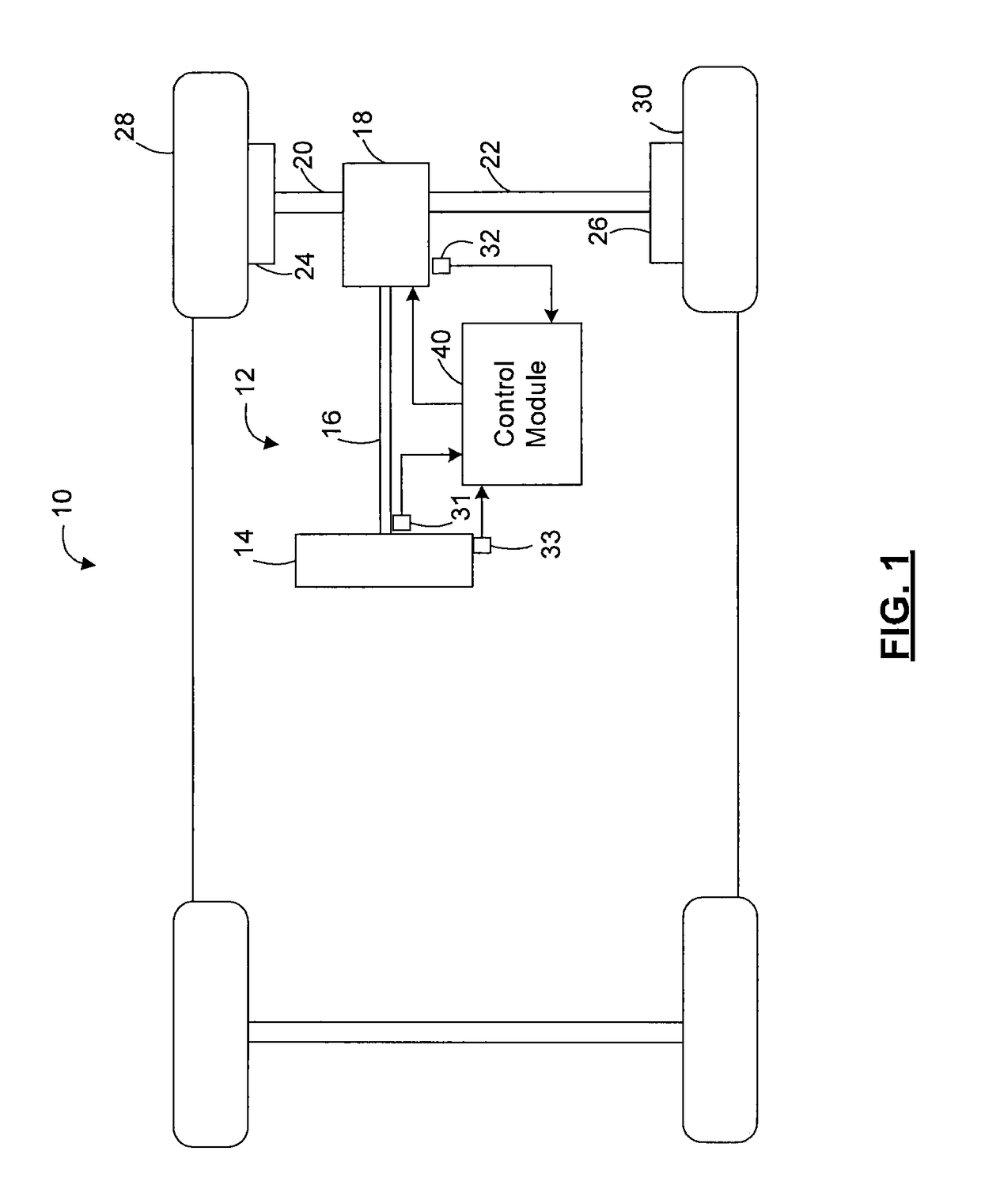
[0015]Referring now to FIG. 1, where the invention will be described with reference to specific embodiments without limiting same, an exemplary embodiment of a vehicle 10 including a steering system 12 is illustrated. In various embodiments, the steering system12 includes a hand wheel 14 coupled to a steering shaft 16. In one exemplary embodiment, the steering system 12 is an electric power steering (EPS) system that further includes a steering assist unit 18 that couples to the steering shaft 16 of the steering system 12 and to tie rods 20, 22 of the vehicle 1. The steering assist unit 18 includes, for example, a rack and pinion steering mechanism (not shown) that may be coupled through the steering shaft 16 to a...


PUM


Abstract

A method of calculating a motor velocity in an electric power steering system comprises receiving a plurality of motor position signals from a motor position sensor of the electronic power steering system, calculating a plurality of angle difference based on the motor position signals prior to performing any filtering operations on the motor position signals, performing a linear regression analysis on the angle differences to predict an angle difference, and calculating a motor velocity based on the predicted angle difference.

Description

CROSS-REFERENCES TO RELATED APPLICATIONS[0001]This patent application claims priority to U.S. Provisional Patent Application Ser. No. 61 / 768,111 filed Feb. 22, 2013 which is incorporated herein by reference in its entirety.BACKGROUND OF THE INVENTION[0002]Motor velocity is an important signal for electronic steering. It is used in the control of the motor as well as in steering related functions such as active damping and inertia compensation. In many systems, the motor velocity signal is obtained by differentiating the motor position signal or the signals used to derive motor position with respect to time. In this case, there is a tradeoff between lag, resolution and noise that can be obtained by setting the period of the differentiation or filtering the signal with a low pass filter. Increasing the differentiation period improves noise and resolution but degrades lag. Filtering with a low pass filter also improves noise and resolution at the expense of lag.[0003]Noise and resoluti...

Claims


Application Information

Patent Timeline
Patent Type & Authority Patents(United States)
IPC IPC(8): B26D5/04G01P3/00G01P3/64B62D5/04G01P3/44
CPCB62D5/046G01P3/64G01P3/44
Inventor COLLIER-HALLMAN, STEVEN J.
Owner STEERING SOLUTIONS IP HLDG
Why Eureka
Try Eureka