
Method to mitigate bit induced vibrations by intentionally modifying mode shapes of drill strings by mass or stiffness changes

a drill string and mode shape technology, applied in the field of intentionally modifying the mode shape of drill strings, can solve the problems of vibration behavior of drill strings and bha, able to damage downhole tools, etc., and achieve the effect of reducing vibrations

Inactive Publication Date: 2018-05-22
BAKER HUGHES INC
View PDF16 Cites 8 Cited by
  • Summary
  • Abstract
  • Description
  • Claims
  • Application Information

AI Technical Summary

Benefits of technology

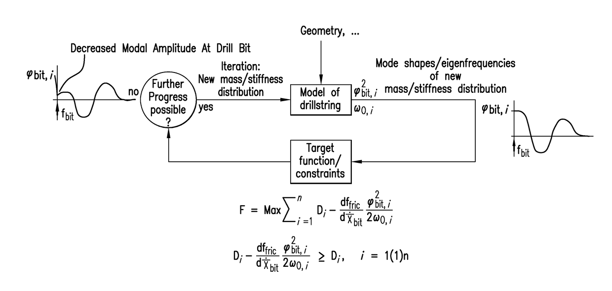
The patent helps to reduce vibrations in a drill tubular which is connected to a drill bit and used to drill a hole in a formation. The method involves creating a mathematical model of the system, including mass distribution, material stiffness and material damping. Then, an equation of motion is created which describes how the drill tubular moves when the drill bit is cutting the formation. This equation of motion is then transformed into a modal domain equation to get the exact shape of the drill tubular at different positions along its length. Compared to this mode shape, a threshold amplitude value is determined and used to modify the mass distribution, material stiffness and material damping if the amplitude exceeds the threshold. This process is iterated until the amplitude is below the threshold and a predetermined constraint limits the modifications. Overall, this technology improves the stability of drilling by reducing vibrations in the drill tubular and improving the trajectory of the hole being drilled.

Problems solved by technology

Applying forces to the drill string to drill a borehole may result in vibratory behavior of the drill string and the BHA.
Recently, high frequency torsional vibrations were observed in field tests with accelerations up to 100 g, which are potentially able to damage downhole tools.

Method used


Image

  • Method to mitigate bit induced vibrations by intentionally modifying mode shapes of drill strings by mass or stiffness changes
  • Method to mitigate bit induced vibrations by intentionally modifying mode shapes of drill strings by mass or stiffness changes
  • Method to mitigate bit induced vibrations by intentionally modifying mode shapes of drill strings by mass or stiffness changes

Examples


Embodiment Construction

[0012]A detailed description of one or more embodiments of the disclosed apparatus and method presented herein by way of exemplification and not limitation with reference to the figures.

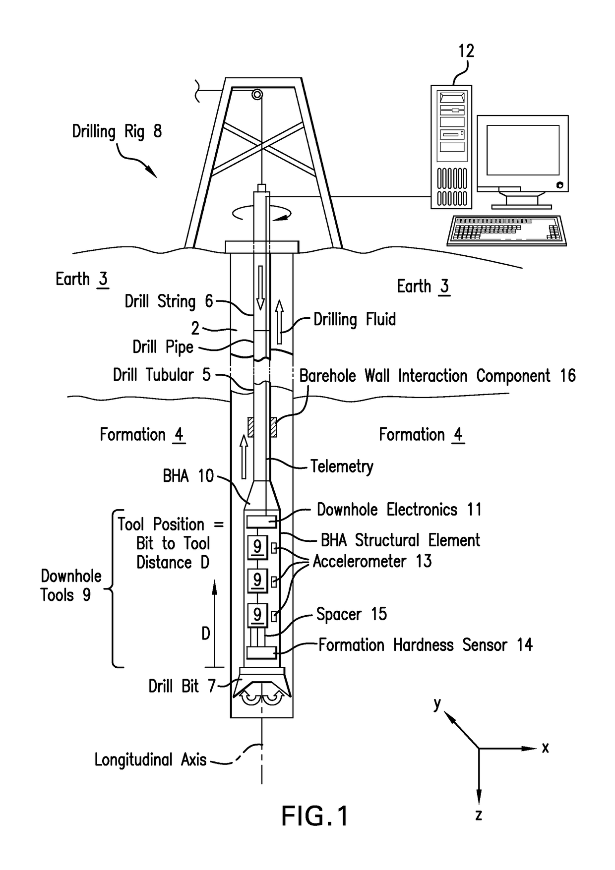
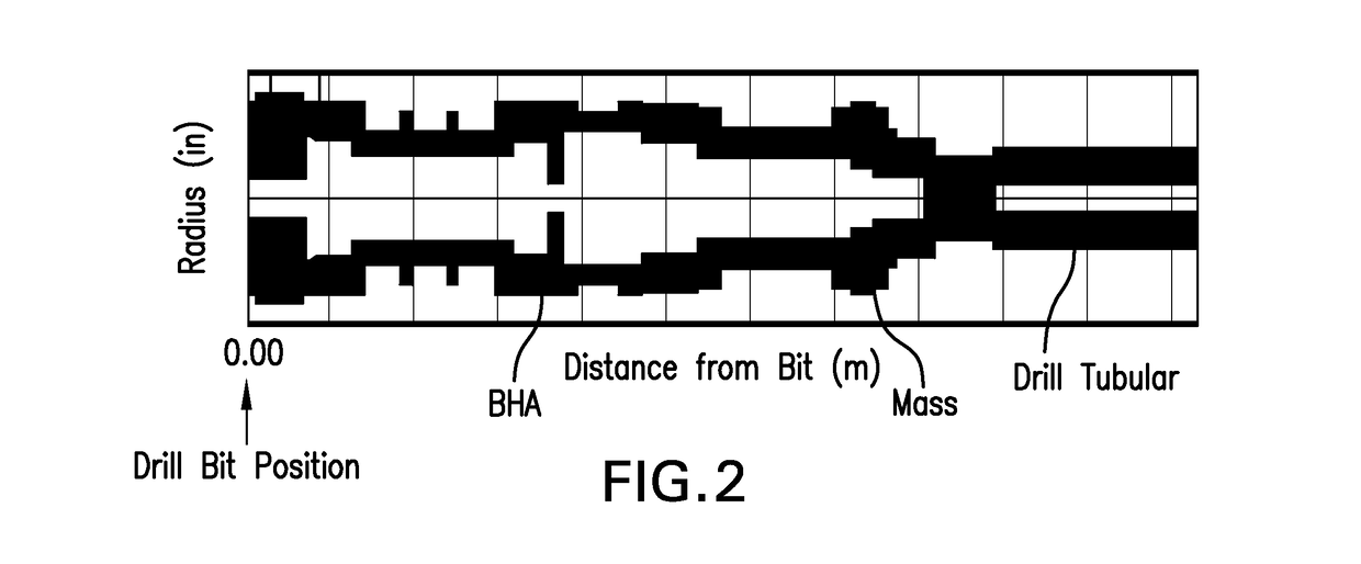
[0013]Disclosed is a method for reducing vibrations in a drill string induced by cutting forces from interaction of a drill bit with an earth formation being drilled. The method is explained using the example of self-excited vibrations due to a falling characteristic of the aggressiveness of the drill bit with respect to the angular velocity of the drill bit or drill string. Nevertheless, the method is also able to reduce vibrations in specific mode shapes, which are induced by any kind of cutting force at the drill bit (e.g., harmonic excitation forces and impacts). The method involves modifying vibratory mode shapes of the drill string, which includes a bottomhole assembly (BHA). The vibratory mode shapes may be modified by changing the distribution of mass, density of mass, structural or material ...


PUM


Abstract

A method for reducing drill tubular vibrations includes: constructing a mathematical model the drill tubular having mass distribution, material stiffness and material damping; constructing an equation of motion of the drill tubular in one of a time domain and frequency domain; transforming the equation of motion into a modal domain equation of motion to provide a mode shape of the drill tubular at an eigenfrequency, the mode shape providing an amplitude at a position along the drill tubular; comparing the amplitude at the position along the drill tubular to a threshold amplitude value; modifying at least one of the mass distribution, material stiffness and material damping if the amplitude exceeds the threshold value; and iterating the above step until at least one of the amplitude of the latest mode shape at the position is less than or equal to the threshold amplitude value and a predetermined constraint limits the modifying.

Description

BACKGROUND[0001]Boreholes are drilled into earth formations for various purposes such as hydrocarbon production, geothermal production, and carbon dioxide sequestration. In general, the boreholes are drilled by rotating a drill bit disposed at the distal end of a string of drill pipes referred to as a drill string. An assembly of the drill bit and other downhole tools at the end of the drill string may be referred to as a bottomhole assembly (BHA). Applying forces to the drill string to drill a borehole may result in vibratory behavior of the drill string and the BHA.[0002]Different kinds of vibratory behavior exist in oil field drilling dynamics. These can be distinguished into axial, torsional, and lateral vibrations. Recently, high frequency torsional vibrations were observed in field tests with accelerations up to 100 g, which are potentially able to damage downhole tools. These vibrations can also be differentiated from stick slip by mode shapes, which are localized to the BHA....

Claims


Application Information

Patent Timeline
Patent Type & Authority Patents(United States)
IPC IPC(8): E21B44/02G06F17/50
CPCE21B44/02G06F17/5086E21B2200/20G06F30/17
Inventor HOHL, ANDREASTERGEIST, MATHIASOUESLATI, HATEMHERBIG, CHRISTIANJAIN, JAYESH J.RECKMANN, HANNOENDRES, LANCE A.
Owner BAKER HUGHES INC
Learn More