Electrical connector

a technology of electrical connectors and connectors, applied in the direction of ohmic resistance heating, conductor screwing into other, bayonets/keyholes, etc., can solve the problems of less advantageous mechanical properties, poisoning of people and the environment, and inacceptable concentrations of lead in waste electrical equipment recycling, etc., to achieve the effect of improving adhesion

Active Publication Date: 2018-05-22
PILKINGTON GRP LTD
View PDF11 Cites 5 Cited by
  • Summary
  • Abstract
  • Description
  • Claims
  • Application Information

AI Technical Summary

Benefits of technology

[0011]An advantage of the invention is that the benefit of improved adhesion with lead-free solder due to a substantially circular foot permanently connected to an angled portion is combined with the benefit of connectivity due to the holding portion. Advantageous embodiments include a holding portion in the shape of a spade connector suitable for a releasable connection. Alternatively, the holding portion in the shape of a ledge or a washer allows a cable to be permanently soldered in position.
is that the benefit of improved adhesion with lead-free solder due to a substantially circular foot permanently connected to an angled portion is combined with the benefit of connectivity due to the holding portion. Advantageous embodiments include a holding portion in the shape of a spade connector suitable for a releasable connection. Alternatively, the holding portion in the shape of a ledge or a washer allows a cable to be permanently soldered in position.

Problems solved by technology

A known problem with such conventional solder is unacceptable concentrations of lead in waste electrical equipment recycling, especially related to end of life vehicles.
High lead concentration in water supplies can cause lead poisoning of people and the environment.
Therefore it is desirable to use a lead-free solder in combination with conventional T-pieces, but this combination has less advantageous mechanical properties, which may lead to breakage of glass in the region of the solder.
Thermal cycling in a vehicle can cause premature failure of such an electrical connection.

Method used


Image

  • Electrical connector
  • Electrical connector
  • Electrical connector

Examples


Embodiment Construction

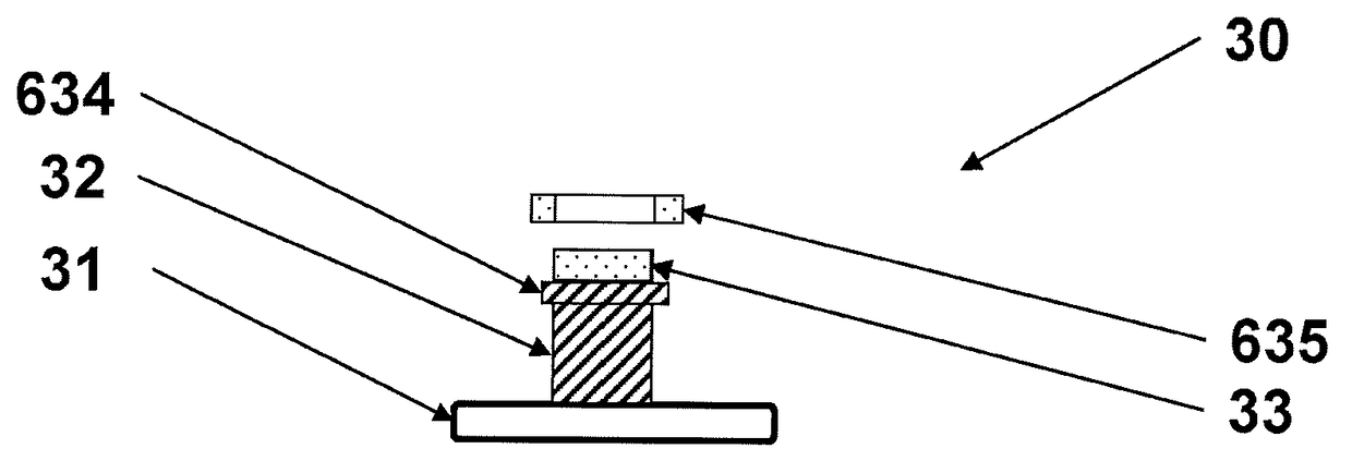
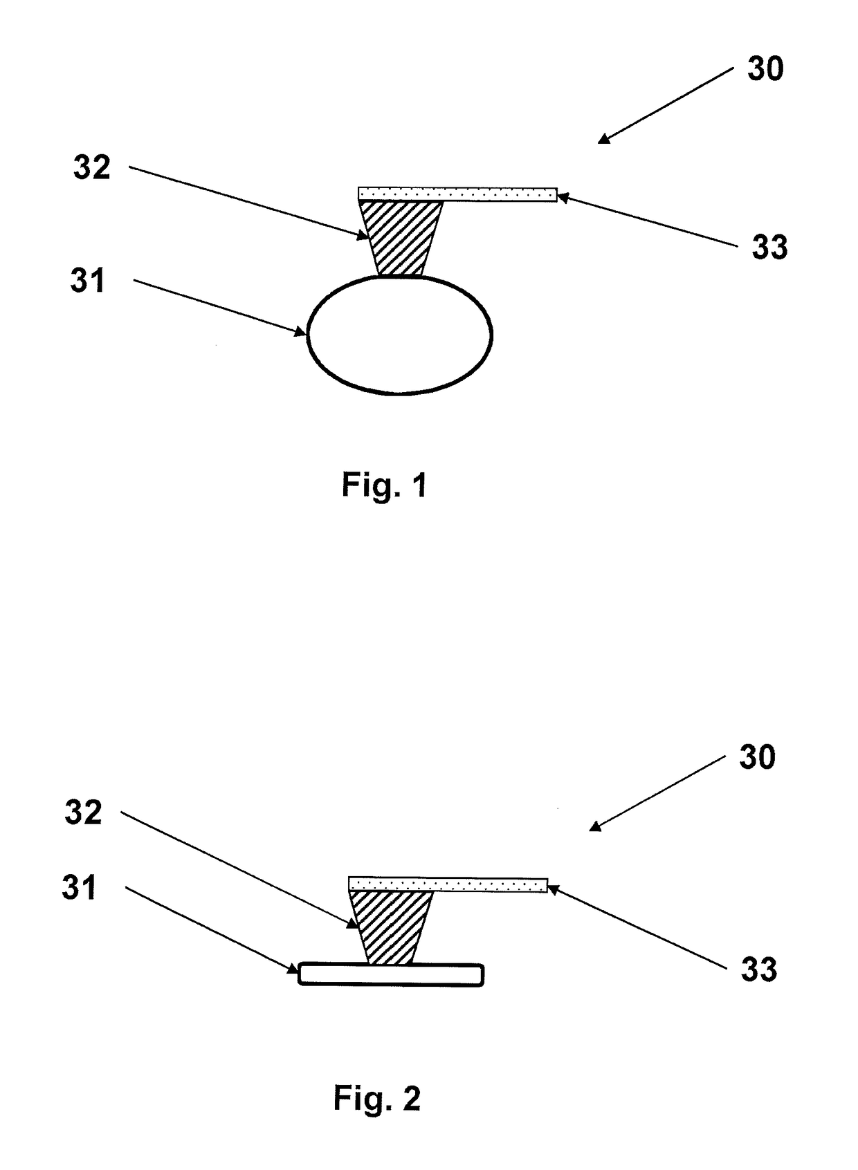
[0033]According to the invention from a first aspect, an electrical connector is provided. FIG. 1 shows an electrical connector 30 according to the invention comprising a foot 31 permanently connected to an angled portion 32. FIG. 2 shows that foot 31 is substantially planar and that the angled portion is substantially at right angles to the plane of the foot 31.

[0034]The shape of the foot 31 is substantially circular or oval. Substantially circular includes circular but with a chord defining a portion of the circular perimeter which is a straight edge. This would be the case, for example, if the foot and the angled portion are made from one piece of sheet metal with a fold.

[0035]The shape of the foot 31 may also be oval shape. The shape of the foot 31 may not be crescent shape, where crescent shape is defined as having perimeter portions wherein the radius of curvature is more than five times other perimeter portions.

[0036]FIG. 1 and FIG. 2 show a holding portion 33 connected to th...


PUM


Abstract

An electrical connector used to make electrical connection to a heating system or to an antenna system on a glazing comprises a substantially planar foot, suitable for soldering, an angled portion, permanently connected to the foot and substantially at right angles to the plane of the foot and a holding portion, connected to the angled portion and suitable for holding a cable, wherein the foot has a substantially circular or oval shape. A glazing comprising such an electrical connector further comprises a sheet of glazing material, an electrical conductor on a surface of the sheet of glazing material and a solder layer between the electrical conductor and the foot wherein the solder layer comprises lead-free solder. The angled portion may be a male portion of a button connector, also known as a snap connector. The holding portion may be a washer soldered or welded to the angled portion.

Description

BACKGROUND OF THE INVENTION[0001]The invention relates to an electrical connector used, for example to make electrical connection to a heating system or to an antenna system on a glazing, and a method of manufacturing a glazing.[0002]Electrical connectors are known which make an electrical connection between a cable and a conductive element on a vehicle glazing. For example, a T-piece connector is used to connect a heating circuit or antenna on a vehicle glazing to the wiring harness of a vehicle. The T-piece comprises at least two feet which are soldered to a conductive element, such as a busbar, on the vehicle glazing. The feet are connected to the busbar using a conventional solder, containing lead.[0003]A known problem with such conventional solder is unacceptable concentrations of lead in waste electrical equipment recycling, especially related to end of life vehicles. High lead concentration in water supplies can cause lead poisoning of people and the environment. Therefore it...

Claims


Application Information

Patent Timeline
Patent Type & Authority Patents(United States)
IPC IPC(8): H01R4/02H01R4/00H01R4/56H05B3/84H01R4/48H01R43/02
CPCH01R4/02H01R4/48H01R4/54H01R43/02H05B3/84H01R4/56H05B2203/017H05B2203/016
Inventor LYON, MICHAELHOUGHTON, JULIE
Owner PILKINGTON GRP LTD
Why Eureka
Try Eureka