
Clipping machine with easy access

a clipping machine and easy-to-access technology, which is applied in the field of clipping machines, can solve the problems of cumbersome handling of the housing portion of the known clipping machine, time-consuming and labor-intensive refilling of the tubular packaging casing on the filling tube, and achieve the effects of shortening the telescopic arrangement, simplifying the design and high functionality and reliability

Active Publication Date: 2018-06-05
POLY CLIP SYST
View PDF8 Cites 4 Cited by
  • Summary
  • Abstract
  • Description
  • Claims
  • Application Information

AI Technical Summary

Benefits of technology

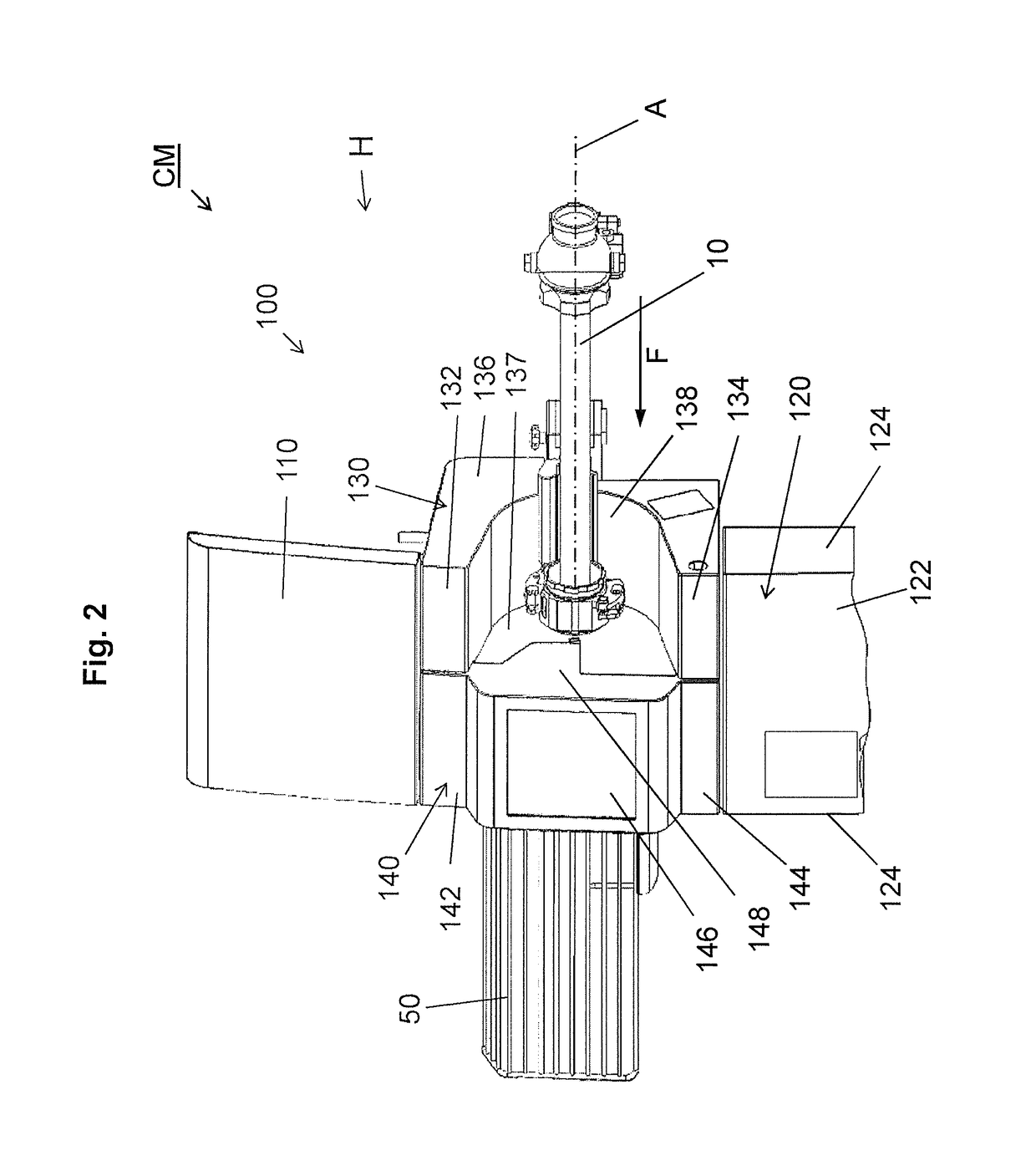
[0011]By means of said shifting mechanism, the housing element may be shifted away from the closing region. The operator does not need to step back from the clipping machine for opening the clipping machine, e.g. during refilling tubular packaging casing to the filling tube, and may directly grasp into the closing region, whereby refilling tubular packaging casing to the filling tube is facilitated. Also, an operator does not need to walk around the opened housing element.
[0029]As an additional safety feature, in a preferred embodiment of the inventive clipping machine, a second sensor device is provided for detecting the presence or absence of the casing brake assembly in an operating position on the filling tube. The second sensor element may prevent operation of the clipping machine in case that the casing brake assembly is not in its operating position, and may allow operation of the clipping machine in case that the casing brake assembly is properly positioned.

Problems solved by technology

The housing portions of the housing of known clipping machines are often cumbersome to handle, e.g. while opening the housing.
Accordingly, opening said housing portions is circumstantial, refilling tubular packaging casing on the filling tube is time consuming and not user friendly.

Method used


Image

  • Clipping machine with easy access
  • Clipping machine with easy access
  • Clipping machine with easy access

Examples


Embodiment Construction

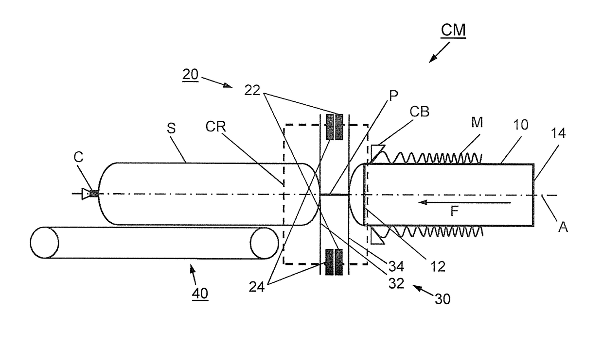
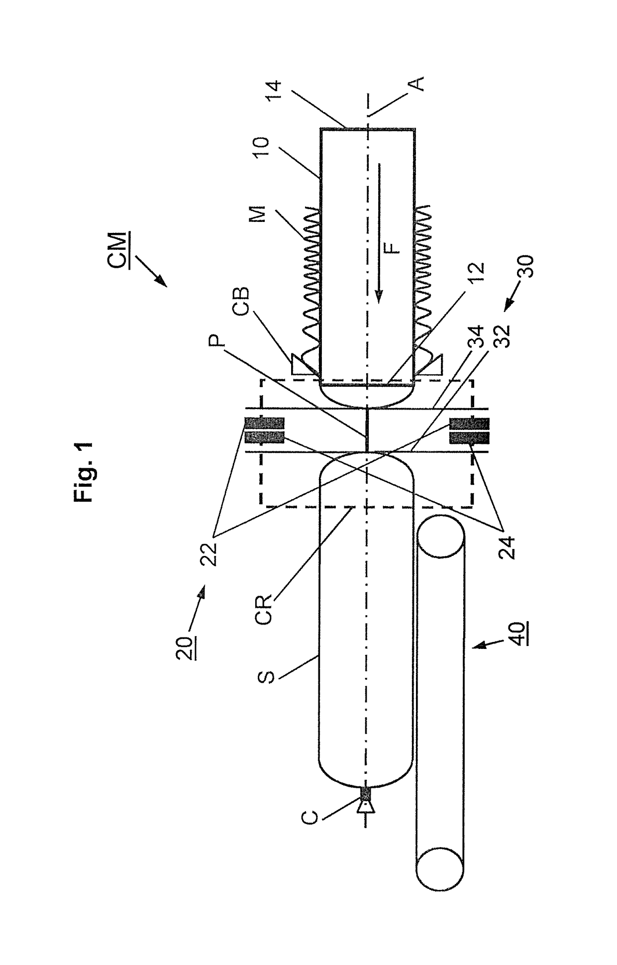
[0039]A clipping machine CM for producing sausage-shaped products S shown in FIG. 1, comprises, as main components, a cylindrical filling tube 10 having a longitudinally extending central axis A and being made of a suitable material, like stainless steel. A tubular packaging casing M made of a thin sheet material is stored on the filling tube 10. Clipping machine CM further includes a clipping device 20 and gathering means 30 for gathering the filled tubular packaging casing M and for forming a plait-like portion P thereto which are arranged downstream filling tube 10. The plait-like portion P is at least approximately free of filling material. Clipping device 20 is provided for closing the filled tubular packaging casing M by applying a closure means, like a closure clip C, to said plait-like portion P. It has to be understood that clipping machine CM includes a control unit for controlling operation of the components of clipping machine CM.

[0040]As further can be inferred from FIG...


PUM

PropertyMeasurementUnit
pressureaaaaaaaaaa
frictional forceaaaaaaaaaa
angleaaaaaaaaaa

Abstract

The present invention relates to a clipping machine for producing sausage-shaped products, like sausages, by filling a tubular or bag-shaped packaging casing with filling material and closing said filled tubular or bag-shaped packaging casing. The clipping machine includes a filling tube through which the filling material is fed into said tubular or bag-shaped packaging casing which is stored on said filling tube, a casing brake assembly arranged on the filling tube for limiting the movement of the tubular packaging casing at least while being filled, gathering means for gathering said filled tubular packaging casing and for forming a plait-like portion thereto, and a clipping device for applying at least one closure means, like a closure clip, to the plait-like portion formed on the filled tubular or bag-shaped packaging casing in a closing region. The clipping machine further comprises a housing defining at least a front wall, a rear wall, and two side walls of the clipping machine, for enclosing at least the clipping device and the gathering means. The housing includes at least one housing element arranged in the front wall of the housing for covering at least the closing region, wherein the at least one housing element is coupled to the clipping machine by a linking device including a shifting mechanism for reversibly shifting the housing element relative to the clipping machine, in a shifting direction, for granting access to the closing region of the clipping machine.

Description

CROSS-REFERENCE TO RELATED APPLICATION[0001]The present application claims the benefit of priority of European Patent Application No. 15202182.0 filed Dec. 22, 2015, the contents of which are incorporated herein by reference in their entirety.FIELD[0002]The present invention relates to a clipping machine for producing sausage-shaped products which includes an improved covering door.BACKGROUND OF THE INVENTION[0003]In practice, it is known that, for example in the production of sausage-shaped products, like sausages, filling material is fed by a filling machine through a filling tube of a clipping machine into a tubular packaging casing which is stored on the filling tube and which is closed at its front end, i.e. the end pointing in the feeding direction of the filling material by a closure means, like a closure clip. The tubular packaging casing is pulled-off from the filling tube while being filled by the feeding pressure. A casing brake applies a frictional force to the tubular p...

Claims


Application Information

Patent Timeline
Patent Type & Authority Patents(United States)
IPC IPC(8): A22C11/00A22C11/02A22C11/12A22C11/10
CPCA22C11/125A22C11/00A22C11/008A22C11/12A22C11/0245A22C11/0263A22C11/10A22C11/02B65B9/12B65B51/04
Inventor EBERT, DETLEFNIKOLEY, WOLFGANG
Owner POLY CLIP SYST
Learn More