Method for determining hydraulic fracture orientation and dimension

a hydraulic fracture and orientation technology, applied in the field of hydraulic fracture, can solve the problems of limiting the effectiveness of microseismic imaging, limiting the efficiency of microseismic imaging, and the tensile opening of hydraulic fractures being less effective at being captured by themselves, so as to achieve the effect of maximizing the efficiency of multi-stage fracture treatmen

Active Publication Date: 2018-06-05
CONOCOPHILLIPS CO
View PDF22 Cites 20 Cited by
  • Summary
  • Abstract
  • Description
  • Claims
  • Application Information

AI Technical Summary

Benefits of technology

[0006]The present invention relates generally to hydraulic fracturing. More particularly, but not by way of limitation, embodiments of the present invention include tools and methods for determining hydraulic fracture orientation and dimensions using downhole pressure sensors. The present invention can monitor evolution of reservoir stresses throughout lifetime of a field during hydraulic fracturing. Measuring and / or identifying favorable stress regimes can help maximize efficiency of multi-stage fracture treatments in shale plays.

Problems solved by technology

As an indirect method, microseismic imaging technique can suffer from a number of issues which limit its effectiveness.
While microseismic imaging can capture shear failure of natural fractures activated during well stimulation, it is typically less effective at capturing tensile opening of hydraulic fractures itself.
Moreover, there is considerable debate on interpretations of microseismic events and how they relate to hydraulic fractures.
In practice, the multiplicity of parameters involved combined with idealized geometries can result in non-unique solutions.

Method used


Image

  • Method for determining hydraulic fracture orientation and dimension
  • Method for determining hydraulic fracture orientation and dimension
  • Method for determining hydraulic fracture orientation and dimension

Examples


example 1

[0035]In this Example, pressure gauges were installed downhole and monitored during multi-stage hydraulic fracturing of horizontal wells in a shale formation located in Eagle Ford Formation located near San Antonio, Tex.

[0036]FIG. 4 shows a configuration of active (Koopmann C1) and offset (Burge A1, Koopman C2) wells and monitoring wells (MW1, MW2) used in this Example. Pressure gauges (100, 110, 120, 130) were installed in two of the wells (Koopmann C1 and Burge A1) as well as both monitoring wells (MW1 and MW2). Initial stages of the multi-stage hydraulic fracturing process start at toe end of the horizontal wells while each subsequent fracturing stage starts closer and closer to heel end of the horizontal well. As illustrated, hydraulic communication between the monitoring wells and Koopmann C1 is present during various fracturing stages 70, 80, and 90.

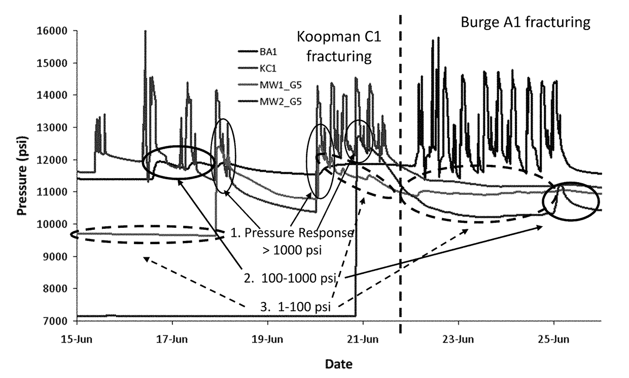
[0037]FIG. 5 plots pressure response recorded by the pressure gauges as a function of time. Koopmann C1 and Burge A1 were subject...


PUM


Abstract

Method for characterizing subterranean formation is described. One method includes: placing a subterranean fluid into a well extending into at least a portion of the subterranean formation to induce one or more fractures; measuring pressure response via one or more pressure sensors installed in the subterranean formation; and determining a physical feature of the one or more fractures.

Description

CROSS-REFERENCE TO RELATED APPLICATIONS[0001]This application is a non-provisional application which claims benefit under 35 USC § 119(e) to U.S. Provisional Application Ser. No. 61 / 917,659 filed Dec. 18, 2013, entitled “METHOD FOR DETERMINING HYDRAULIC FRACTURE ORIENTATION AND DIMENSION,” which is incorporated herein in its entirety.FIELD OF THE INVENTION[0002]The present invention relates generally to hydraulic fracturing. More particularly, but not by way of limitation, embodiments of the present invention include tools and methods for determining hydraulic fracture orientation and dimensions using downhole pressure sensors.BACKGROUND OF THE INVENTION[0003]Hydraulic fracturing is an economically important stimulation technique applied to reservoirs to increase oil and gas production. During hydraulic fracturing stimulation process, highly pressurized fluids are injected into a reservoir rock. Fractures are created when the pressurized fluids overcome the breaking strength of the ...

Claims


Application Information

Patent Timeline
Patent Type & Authority Patents(United States)
IPC IPC(8): E21B43/26E21B47/06
CPCE21B43/26E21B47/06
Inventor ROUSSEL, NICOLAS PATRICKFLOREZ, HORACIORODRIGUEZ, ADOLFO ANTONIOAGRAWAL, SAMARTH
Owner CONOCOPHILLIPS CO
Why Eureka
Try Eureka