

Auto nulling of induction balance metal detector coils
a metal detector and auto-null technology, applied in the field of induction balanced metal detector search coils, can solve the problems of noise, increase in null voltage, and both methods suffer from increased null voltage, and achieve the effect of improving the null voltage of the signal received
- Summary
- Abstract
- Description
- Claims
- Application Information
AI Technical Summary
Benefits of technology
Problems solved by technology
Method used
Image

Examples
Embodiment Construction
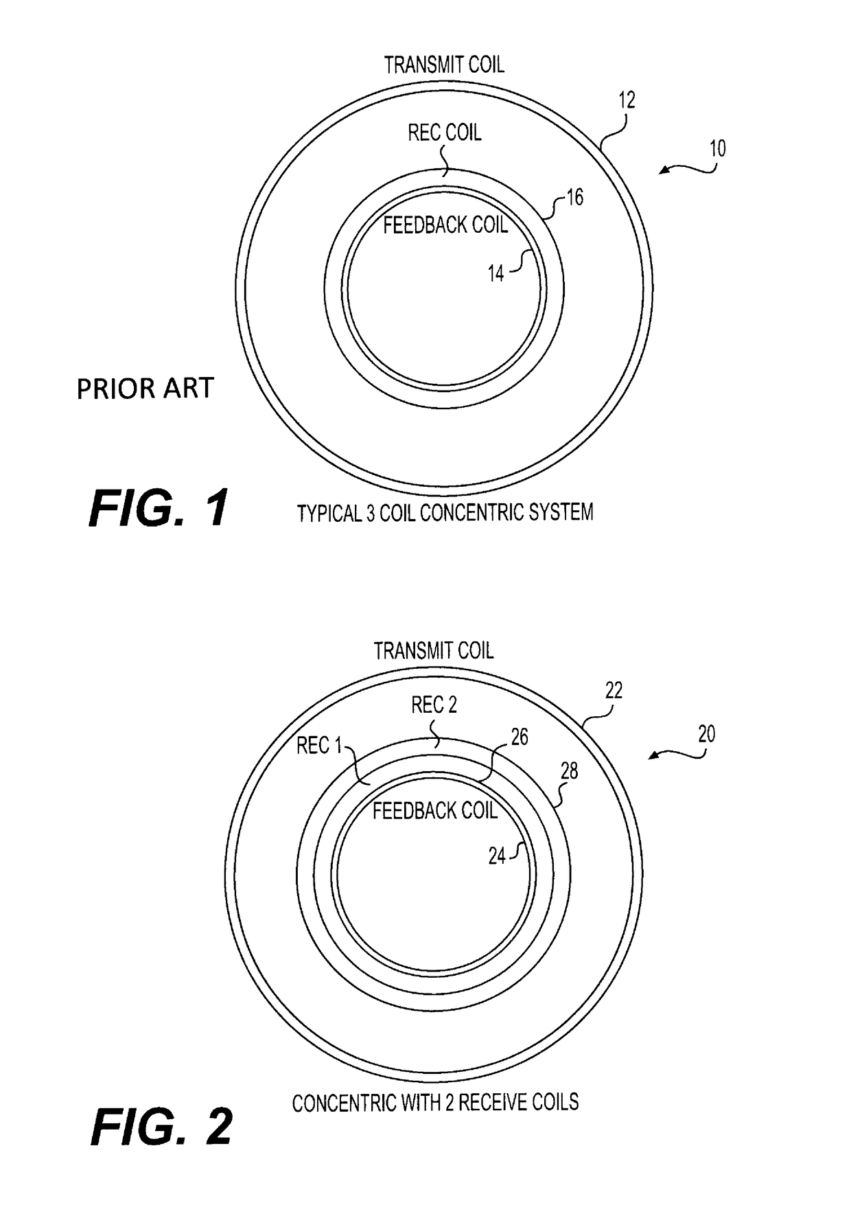
[0029]FIG. 1 illustrates the concentric coil arrangement in the typical 3 coil system 10. The main outer primary coil 12 induces a magnetic field in the ground. An inner bucking or primary feedback coil 14 is adjacent secondary receiving coil 16.
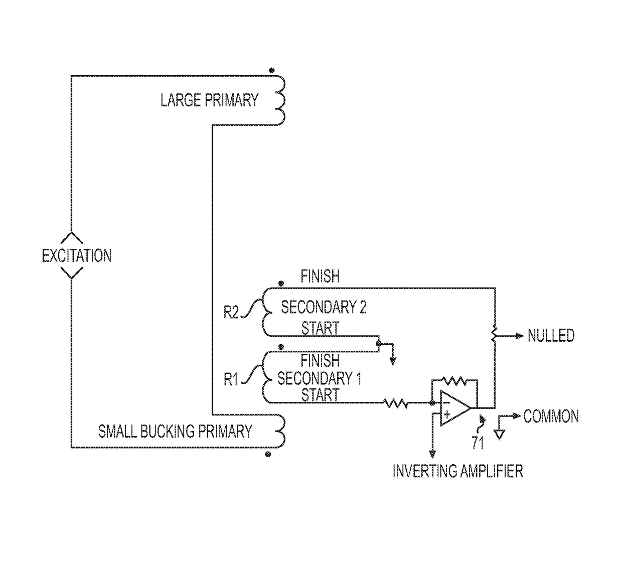
[0030]FIG. 2 illustrates the concentric coil arrangement 20 of the invention with an outer primary coil 22, an, inner bucking or feedback coil 24 and two adjacent secondary receiving coils, receive 1, 26 and receive 2, 28.
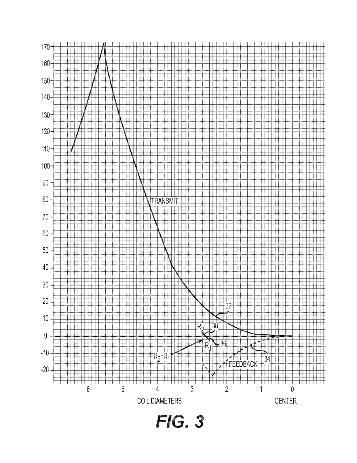
[0031]In this new coplanar concentric coil system 20, the inductive coupling coefficient between coils is approximately equal to the cube of the diameters. Thus, the first inner receive secondary coil 26 is closest to the inner primary feedback coil 24, producing an over nulled signal. The second receive coil 2, secondary coil 28, which is on top or outside of the first inner receive secondary coil 26, is further away from the feedback primary coil 24. Therefore, the second receive coil 28 is undernulled.
[0032]The overnulle...
PUM
 Abstract
Description
Claims
Application Information