Optical mounting device

a technology of optical mounting and mounting bracket, which is applied in the direction of instruments, stands/trestles, camera body details, etc., can solve the problems of limiting the range of up/down rotation, affecting the operation of the camera, and the existing gimbal mounts have some disadvantages, etc., to achieve precise adjustable clamping force, simplified control, and quick operation

Inactive Publication Date: 2018-06-05
RIDDEL CHARLES STEPHEN +1
View PDF16 Cites 7 Cited by
  • Summary
  • Abstract
  • Description
  • Claims
  • Application Information

AI Technical Summary

Benefits of technology

[0009]It is an object of the present application to provide an optical mounting device configured to equalize rotation forces on the horizontal and vertical axes in a manner that incorporates precise adjustable clamping forces and simplified controls for quick operation.
[0010]It is another object of the present application to provide an optical mounting device configured to provide a method and configuration that permits balancing of the optical instrument about the axes while minimizing flexure and vibration. It is desired that the use of long quick-plates is unnecessary. The configuration of the optical mounting device allows location adjustment of the optical instrument in a plurality of directions to ensure proper balance. Removal of the long quick-plates minimizes flexure and vibration to help ensure better viewing quality.
[0011]It is another object of the present application to provide for better control and functionality of the optical instrument when in use. The optical mounting device of the present application is configured to enhance control of short instruments as well as allow rotation of the optical instrument between both portrait and landscape orientations.

Problems solved by technology

Existing gimbal mounts tend to be heavy and bulky.
However, existing gimbal mounts have some disadvantages.
They typically limit the range of up / down rotation and fail to accommodate wide instrument loads in an acceptable manner.
Generally, such gimbal mounts also fail to provide a steering mechanism for short instruments.
Additional limitations include cumbersome clutch adjustments; failure to provide for portrait mode photography; and depend on long quick-plates for fore / aft balance adjustments.
While this may seem good, long quick-plates tend to introduce flexure and vibration into the assembly which can affect picture quality.
Furthermore, this flexure and vibration can lead to dislodging of the optical instrument from the clamping device.
The knob controls on existing gimbal mounts are difficult to adjust quickly and are not precise.

Method used


Image

  • Optical mounting device
  • Optical mounting device
  • Optical mounting device

Examples


Embodiment Construction

[0020]Illustrative embodiments of the preferred embodiment are described below. In the interest of clarity, not all features of an actual implementation are described in this specification. It will of course be appreciated that in the development of any such actual embodiment, numerous implementation-specific decisions must be made to achieve the developer's specific goals, such as compliance with system-related and business-related constraints, which will vary from one implementation to another. Moreover, it will be appreciated that such a development effort might be complex and time-consuming but would nevertheless be a routine undertaking for those of ordinary skill in the art having the benefit of this disclosure.

[0021]In the specification, reference may be made to the spatial relationships between various components and to the spatial orientation of various aspects of components as the devices are depicted in the attached drawings. However, as will be recognized by those skille...


PUM


Abstract

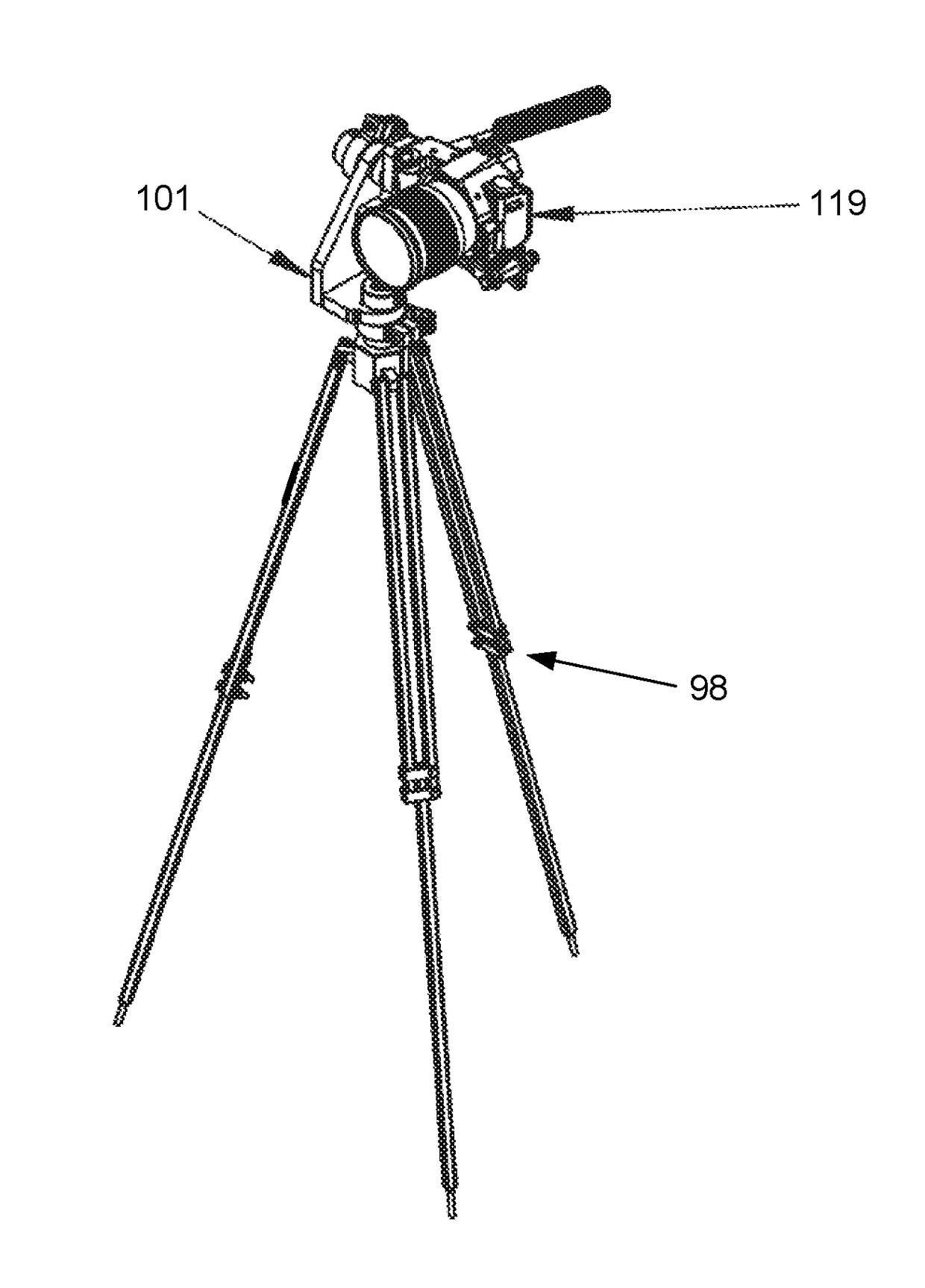
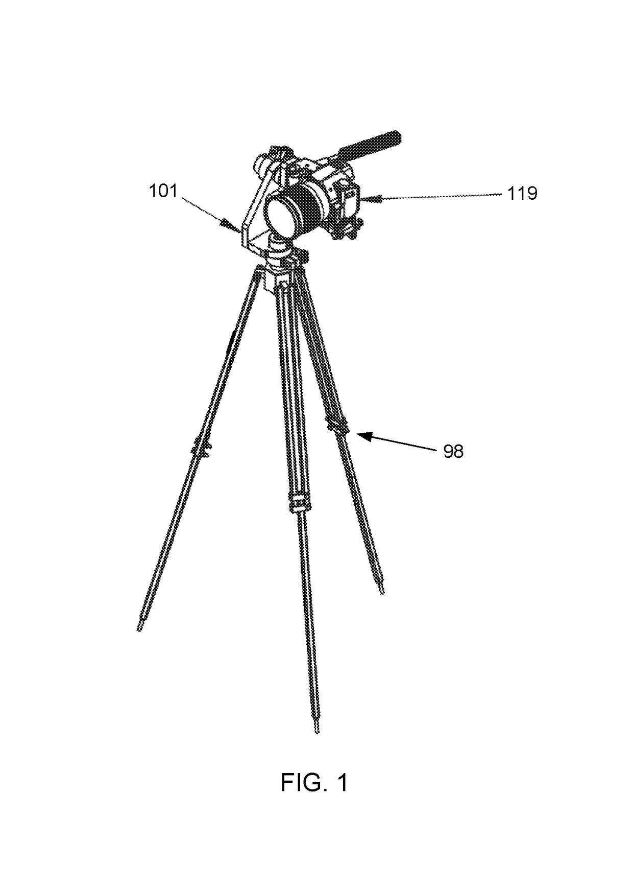
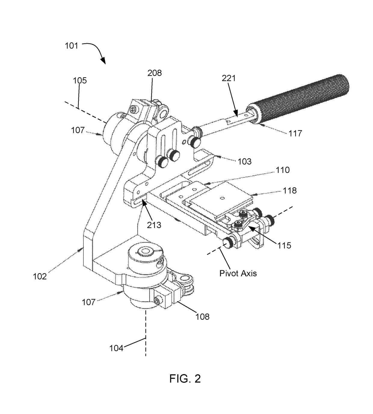
An optical mounting device is disclosed that enables an optical device to be pointed in the desired orientation with minimal effort between a horizontal and a vertical position. The device includes a yoke, a saddle, and a payload platform assembly. The device can lock the position of the optical device into a desired orientation. The payload platform assembly has a lower base that is coupled to the saddle and an extendable upper section attached to a rotation pivot guide that allows the upper section to rotate up to 90 degrees from horizontal landscape orientation to a vertical portrait orientation.

Description

CLAIM OF PRIORITY[0001]This application claims the benefit of U.S. Provisional Application No. 62 / 364,226, filed 19 Jul. 2016. The information contained therein is hereby incorporated by reference.BACKGROUND1. Field of the Invention[0002]The present application relates to optical equipment, and more particularly to an optical mounting device.2. Description of Related Art[0003]Existing gimbal mounts tend to be heavy and bulky. These are used to secure an optical instrument to a stand. They may be configured to provide some degrees of motion and operate to assist in controlling and stabilizing the optical instrument. However, existing gimbal mounts have some disadvantages. They typically limit the range of up / down rotation and fail to accommodate wide instrument loads in an acceptable manner. Generally, such gimbal mounts also fail to provide a steering mechanism for short instruments. Additional limitations include cumbersome clutch adjustments; failure to provide for portrait mode p...

Claims


Application Information

Patent Timeline
Patent Type & Authority Patents(United States)
IPC IPC(8): G03B17/00F16M11/12G03B17/56
CPCG03B17/561G03B17/563F16M11/12F16M2200/022F16M11/105F16M11/16F16M11/2064F16M11/2085F16M11/2092F16M11/32F16M13/00F16M2200/041
Inventor RIDDEL, CHARLES STEPHENRIDDEL, JACOB DANIEL
Owner RIDDEL CHARLES STEPHEN
Why Eureka
Try Eureka