Cooling structure of oil cooling motor

a technology of oil cooling motor and cooling structure, which is applied in the direction of engine components, cooling/ventilation arrangement, mechanical equipment, etc., can solve the problems of hot issues such as the cooling method or the cooling efficiency, and achieve the effect of improving bearing performance and improving durability of the motor

Active Publication Date: 2018-06-05
HYUNDAI MOBIS CO LTD
View PDF16 Cites 2 Cited by
  • Summary
  • Abstract
  • Description
  • Claims
  • Application Information

AI Technical Summary

Benefits of technology

[0009]An embodiment of the present invention is directed to a cooling structure of an oil cooling motor capable of improving durability of the motor by supplying oil scattered to a wall surface to a bearing in addition to oil directly churned into the bearing, temporarily storing the supplied oil, and improving bearing performance.

Problems solved by technology

In the case of a general motor of 15 to 20 kW or more, the motor is insufficiently cooled by an air cooling type and therefore is cooled by a water cooling type or an oil cooling type.
Therefore, in the case of the motor of 15 to 20 kW or more, the cooling method or the cooling efficiency becomes a hot issue on the design of the motor.

Method used


Image

  • Cooling structure of oil cooling motor
  • Cooling structure of oil cooling motor
  • Cooling structure of oil cooling motor

Examples


Embodiment Construction

[0027]Hereinafter, example embodiments of the present invention will be described in detail with reference to the accompanying drawings.

[0028]As discussed above, in the case of the motor of 15 to 20 kW or more, the cooling method or the cooling efficiency becomes a hot issue on the design of the motor.

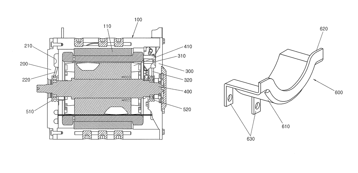
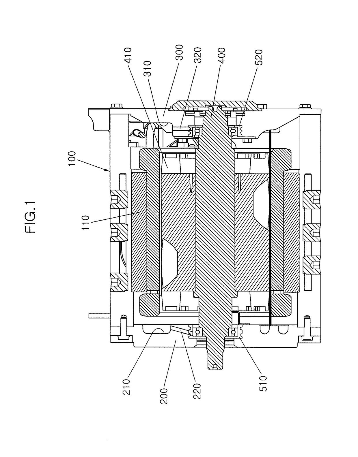
[0029]That is, since the motor cooling method of an example of a hybrid vehicle adopts a method of making oil flow in a top portion of the motor by pumping in the state in which half of a bottom portion of a stator within the motor is dipped in cooling oil and making the oil flow in a lower end thereof through a cooling passage disposed at the stator side by gravity, the motor cooling method may effectively cool the stator but may not effectively cool heat generation of a rotor or a permanent magnet due to an eddy current.

[0030]Further, a method of forming a passage in the rotor to inject oil in a hollow direction of a shaft and scattering the oil due to churning and centrifugal force ...


PUM


Abstract

A cooling structure of an oil cooling motor may include a housing, a front cover and a rear cover each mounted at both sides of a housing along a length direction of the housing, a rotor shaft extending through the housing and have both ends rotatably supported by bearings of the front cover and the rear cover, a rotor disposed in the housing and rotatably supported by the rotor shaft, a front oil supply groove and a rear oil supply groove formed on opposing inner sides of the front cover and the rear cover and configured to temporarily store oil stored in a bottom of the housing and scattered by churning of the rotor, and a front cover passage and a rear cover passage configured to communicate with the front oil supply groove and the rear oil supply groove, respectively.

Description

CROSS-REFERENCE(S) TO RELATED APPLICATIONS[0001]This application claims priority to Korean Patent Application No. 10-2013-0133481, filed on Nov. 5, 2013, which is incorporated herein by reference in its entirety.BACKGROUND[0002]Field[0003]The present disclosure relates to a cooling structure of an oil cooling motor, and particularly, to a cooling structure of an oil cooling motor capable of improving cooling efficiency of an oil cooling motor.[0004]Description of Related Art[0005]Recently, an environmental-friendly hybrid vehicle, including a motor in addition to an engine as a driving source for driving a vehicle, has excellent fuel efficiency and therefore has been released as a future vehicle.[0006]The motor equipped in the hybrid vehicle is inevitably cooled. In the case of a general motor of 15 to 20 kW or more, the motor is insufficiently cooled by an air cooling type and therefore is cooled by a water cooling type or an oil cooling type.[0007]In the case of the motor (15 to 2...

Claims


Application Information

Patent Timeline
Patent Type & Authority Patents(United States)
IPC IPC(8): H02K5/15F16C33/66H02K9/19H02K5/20H02K5/173F16N31/02
CPCH02K9/19F16C33/664F16N31/02H02K5/20H02K5/1732H02K5/15F16C33/6659H02K5/203H02K5/16B60K2001/006B60Y2200/91B60Y2200/92H02K2205/09Y02T10/62Y02T10/64
Inventor KIM, SUNG-CHUL
Owner HYUNDAI MOBIS CO LTD
Why Eureka
Try Eureka