Electron spectrometer

a technology of electron spectrometer and photoelectron, which is applied in the field of photoelectron spectrometer, can solve the problems of difficult sample rotation, still suffer from some distortion in recorded images, and can observe extremely minute crystallites, so as to improve the quality of recorded images and less distortion

Active Publication Date: 2018-06-12
MB SCI
View PDF8 Cites 9 Cited by
  • Summary
  • Abstract
  • Description
  • Claims
  • Application Information

AI Technical Summary

Benefits of technology

[0009]In order to improve the quality of the recorded images, the present inventor has devised a novel device which also eliminates the need for sample manipulation and in addition provides less distortion.

Problems solved by technology

However, in recent years the illumination systems have reached a much higher level of spatial resolution which means that extremely minute crystallites can be observed.
Thereby the manipulation, i.e. rotation of the sample becomes very difficult.
Despite the fact that this system eliminated the need for sample manipulation, it still suffers from some distortion in the recorded images.

Method used


Image

  • Electron spectrometer
  • Electron spectrometer
  • Electron spectrometer

Examples


Embodiment Construction

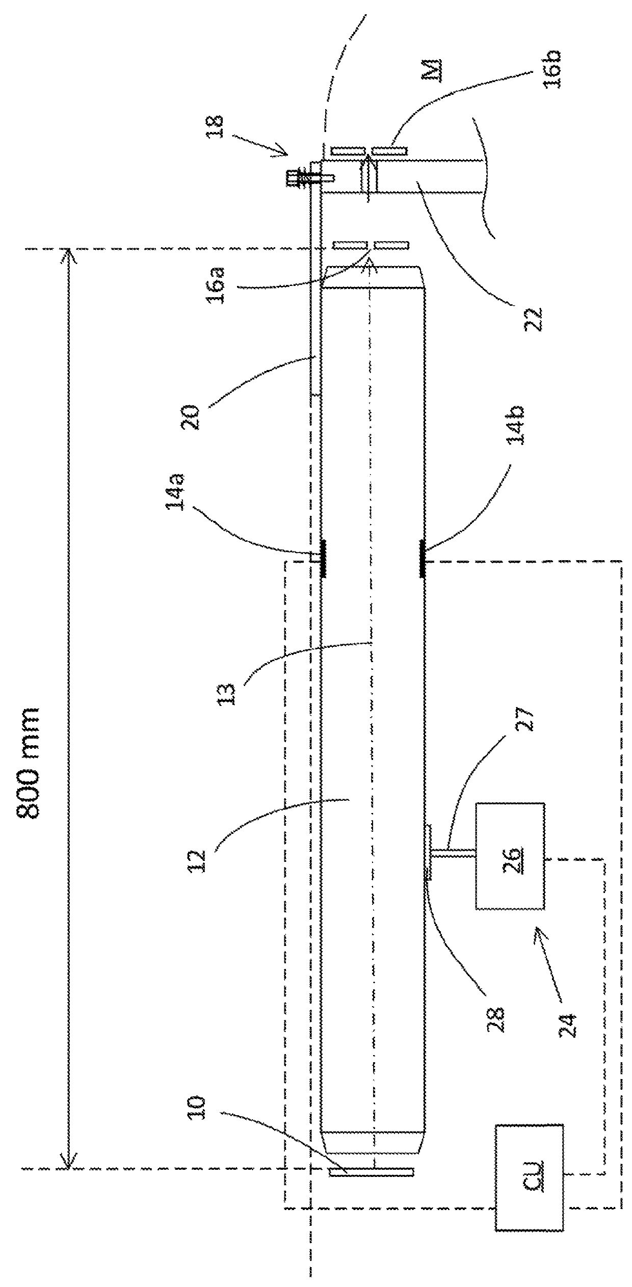
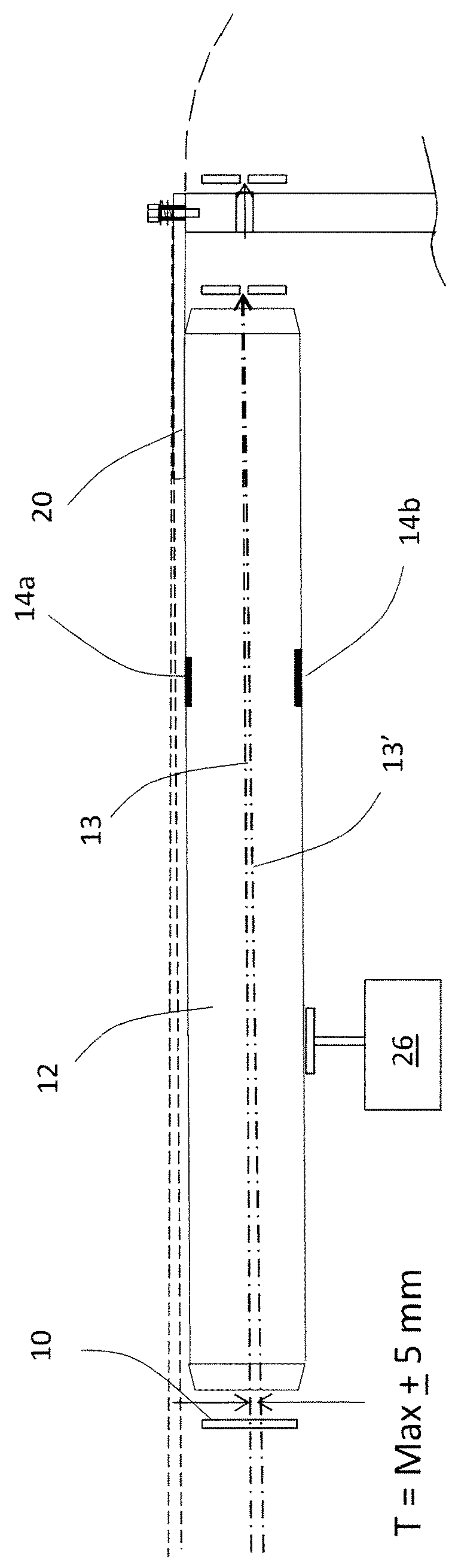
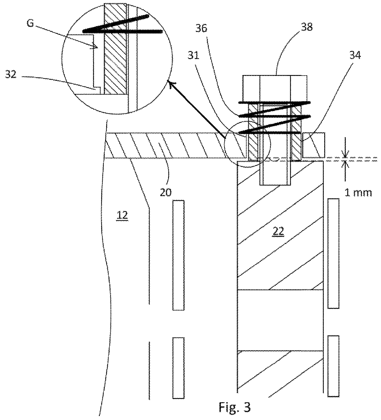
[0056]FIG. 1 illustrates schematically a part of an electron spectrometer embodying the invention, namely the sample 10, the electron lens 12 having an optical axis 13, a pair of deflectors 14a, 14b, an entrance slit 16a to the measurement region of a hemispherical analyser M (only indicated with a broken line), a hinge mechanism 18 suspending the lens 12 in a multi-directional pivot point, via a beam 20 rigidly attached to the body of the lens 12. The hinge 18 is attached to the base plate 22 of the hemispherical analyser M. Inside the measurement region there is a second slit 16b.

[0057]The novelty of the apparatus resides in a preferred embodiment in a tilting mechanism 24. This mechanism in a first embodiment comprises a motor 26, preferably an electric motor, preferably a stepper motor.

[0058]The motor is controlled by a control unit CU that also controls the voltages on the deflectors 14a, 14b, the control being schematically indicated with broken lines, and will be described f...


PUM


Abstract

A charged particle spectrometer of hemispherical analyzer type for analyzing a particle emitting sample, the spectrometer comprising at least a first mechanism configured to move at least a part of the lens with respect to the axis between the sample spot and the analyzer entrance in a coordinate direction synchronously with a deflection of the particle beam.

Description

[0001]The present invention relates to electron spectrometers in general, and in particular to a novel means and method for operating in angular mode.BACKGROUND OF THE INVENTION[0002]In a photo-electron spectrometer of hemispherical analyzer type, a central component is the measurement region in which the energies of the electrons are analysed. The measurement region is formed by two concentric hemispheres, mounted on a base plate, and with an electrostatic field applied between them. The electrons enter the measurement region through an entrance and electrons entering the region between the hemispheres with a direction close to perpendicular to the base plate are deflected by the electrostatic field, and those electrons having a kinetic energy within a certain range defined by the deflecting field will reach a detector arrangement after having travelled through a half circle. In a typical instrument, the electrons are transported from their source (typically a sample that emits ele...

Claims


Application Information

Patent Timeline
Patent Type & Authority Patents(United States)
IPC IPC(8): H01J49/44H01J49/06
CPCH01J49/067H01J49/44G01N2223/32
Inventor BALTZER, PETER
Owner MB SCI
Why Eureka
Try Eureka