Multiple purpose wringer and method of wringing articles

Inactive Publication Date: 2000-03-07
MICRONOVA MFG INC
View PDF19 Cites 5 Cited by
  • Summary
  • Abstract
  • Description
  • Claims
  • Application Information

AI Technical Summary

Benefits of technology

The present invention is helpful in overcoming the shortcomings of the prior art in a number of ways. First, the flexible web conforms to the shape of the wringable item, thereby accommodating a variety of types, shapes and sizes of wringable items. By conforming to the shape of the item, the flexible web evenly distributes wringing pressure on the item, thereby wringing a higher volume of water or solvent than conventional wringers.
Secondly, the versatile, flexible web can be adjusted to accommodate small items that could not be accommodated by other wringers.
Thirdly, the present invention is generally easy to clean. The number of openings, corners and shelv

Problems solved by technology

Standard wringers generally do not apply a uniform wringing pressure to a mop or other wringable items.
However, for a string mop, for example, or a flap mop, placed on the perforated pan of the wringer, the strings take whatever shape they can given the shape of the sides and bottom of the wringer, but the strings will not necessarily conform in every respect to the shape of the wringer.
However, for those parts of the string mop which may move or readjust during the process of wringing, such as by squeezing out the sides or moving toward the bottom of the wringer, the full wringing action may not be applied to those parts.
Therefore, a uniform wringing of solution from the mop may not be achieved because of happenstance variations in the shape of the strings.
Typical wringers such as the gear press wringer are also limited in the number of different configurations of mops that can be accommodated

Method used


Image

  • Multiple purpose wringer and method of wringing articles
  • Multiple purpose wringer and method of wringing articles
  • Multiple purpose wringer and method of wringing articles

Examples


Embodiment Construction

The present invention of a multiple purpose wringer provides a versatile wringer which can wring a wide variety of types and sizes of mops, wipes, sponges and other wringable materials through a relatively simple mechanism which is easy to clean and minimizes any possible creation of secondary contaminants such as metal particles or lubricants.

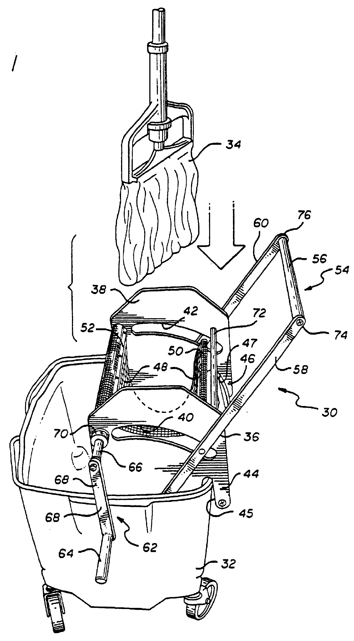
One preferred embodiment of a wringer 30 in accordance with the present invention is shown in FIG. 1 on a bucket 32. The wringer 30 is shown in an open position and is ready to receive a mop 34. The wringer in the preferred embodiment has first and second stainless steel side plates 36, 38 forming part of a frame for purposes of rigidity and stability which have side plate slots 40, 42 and first and second bucket mounts 44, 46. A web 48 is positioned in the frame so that the web can accept a wringable item and close around the wringable item so as to wring the item, preferably by applying uniform pressure over as much of the item as possible. ...


PUM


Abstract

An adjustable wringer can wring a variety of different types and sizes of mops, wipes, sponges and other wringable items for use in cleaning clean rooms. The wringer has two side plates situated in a spaced relationship relative to one another, each of the side plates having a slot. The wringer has a lever which has a handle and a rod. The handle has side posts, with the lower end of each side post being rotatably mounted to a respective side plate, and a handle bar extending across and connecting the upper ends of the first and second side posts. The rod is attached at each end to a handle side post, with each end of the rod passing through a respective slot in the side plates. The wringer also has a crank which has a crank handle and a rotatable crank shaft that extends from one side plate to the other. A substantially lint-free, flexible web is attached at one end to the rod and at the other end to the crank shaft. Once a wringable item has been placed in the wringer, the rod may be moved adjacent to the crankshaft. The crank handle may then be rotated to tighten the flexible web about the wringable item, thereby wringing the item. The wringer may additionally include low-friction bushings to replace the lubricating oils and greases typically found in wringers, thereby making the wringer suitable for sterilization in an autoclave.

Description

BACKGROUND OF THE INVENTION1. Field of the InventionThe present invention relates to wringers such as for use in clean rooms, and particularly to a versatile, wringer that can wring a variety of types and sizes of mops, wipes, sponges and other wringable materials.2. Description of Related ArtCertain pharmaceuticals, electronics and other specialized goods must be manufactured in contamination-free "clean rooms" which are kept free from impurities such as dust and microorganisms. Similarly, hospitals maintain their operating rooms as "clean rooms", which must be kept free form microorganisms and dust particles, and all reusable items must be sterilized in high-heat autoclaves prior to reuse in the sterile environment of an operating room.In typical procedures for maintaining the contamination-free environment of a clean room, cleaning crews that regularly mop and wipe the room use a bucket of cleaning solution, a mop and a wringer along with sponges. Sponges are usually rinsed and s...

Claims


Application Information

Patent Timeline
IPC IPC(8): A47L13/10A47L13/59
CPCA47L13/59
Inventor DE GUZMAN, JOSELITO
Owner MICRONOVA MFG INC
Why Eureka
Try Eureka