
Synthetic infiltration collection system

a collection system and synthetic technology, applied in the direction of filtration separation, water cleaning, separation processes, etc., can solve the problems of biological fouling of intake pipes, high water production costs, waste of resources, etc., and achieve the effect of eliminating local dependency and high quality

Inactive Publication Date: 2007-05-17
JONES ANTHONY +1
View PDF18 Cites 27 Cited by
  • Summary
  • Abstract
  • Description
  • Claims
  • Application Information

AI Technical Summary

Benefits of technology

[0011] The inventive filtered seawater collection system provides high quality water without being dependent upon local nearshore geology. The system also provides water volumes much higher than systems that depend upon indirect intakes that are dependent on nearshore geology. The inventive system's ability to eliminate dependency on local nearshore geology allows it to be placed in coastal areas of the world where the nearshore geology renders indirect intakes an impossibility.
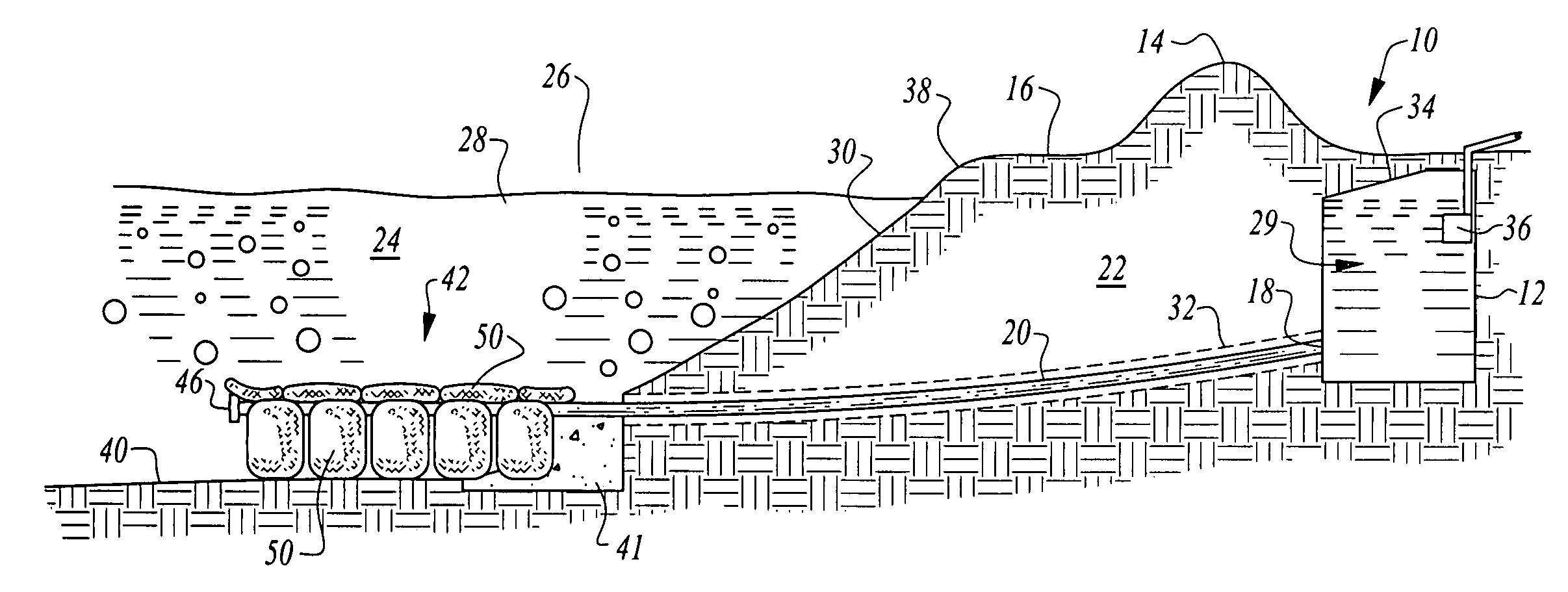
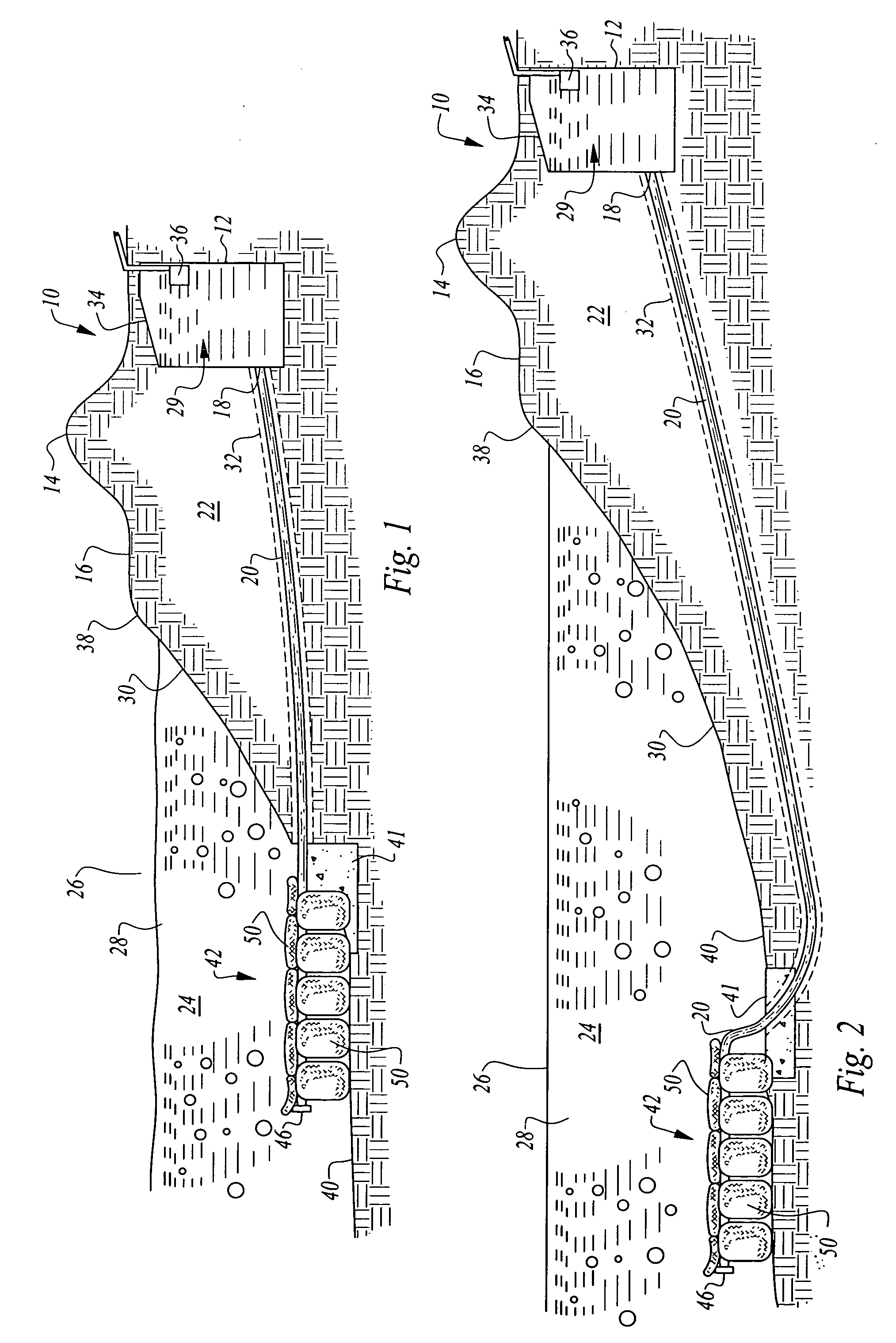
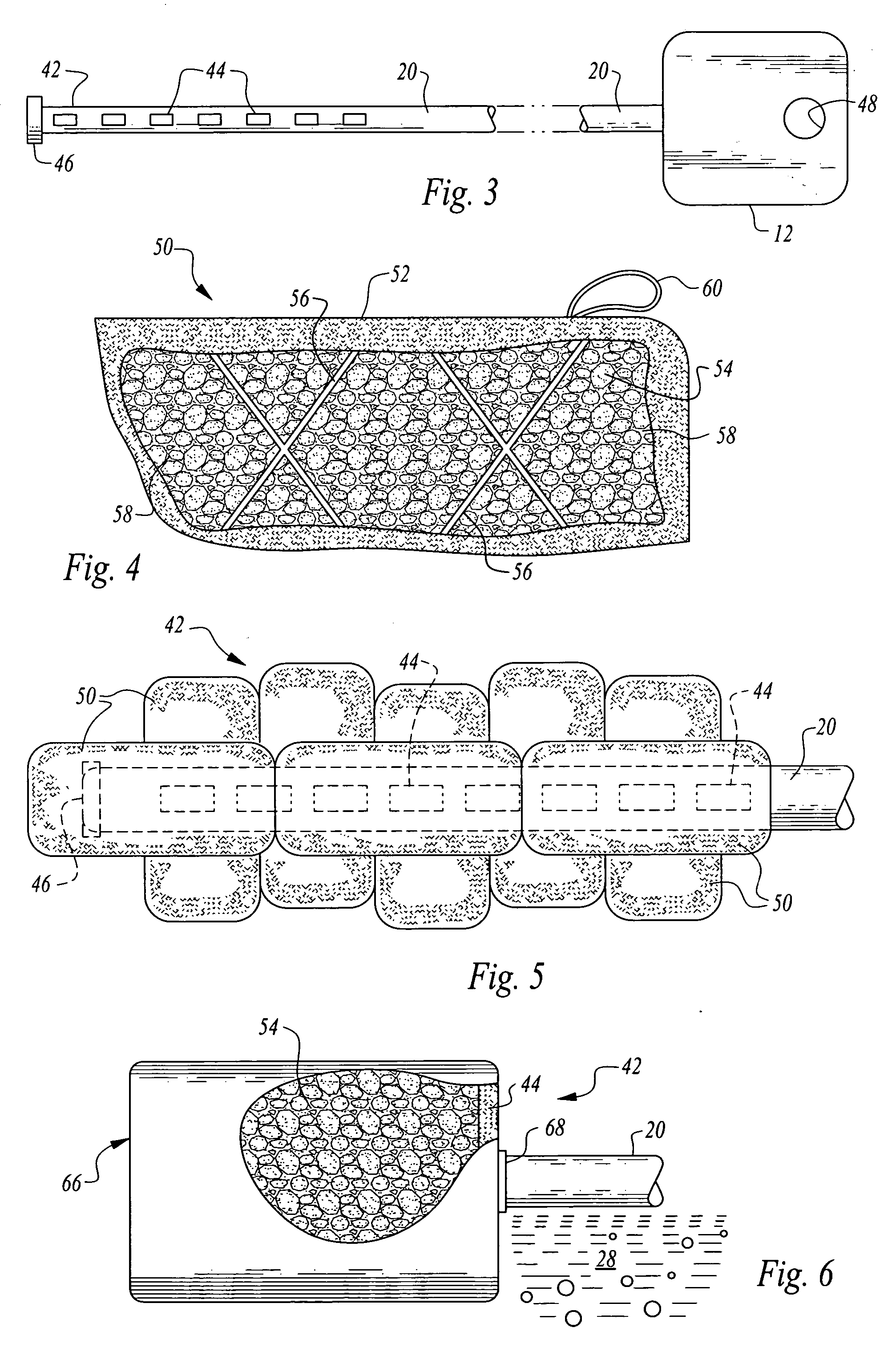
[0013] The pipe extends from the reservoir out past the nearshore and into the open ocean where it is preferably anchored to the sea floor. The opposite end of the pipe terminates at an intake area where the pipe is perforated with a plurality of openings. Geological materials, preferably gravel, are filled into porous containers and enclosed therein. The containers are then lowered precisely upon the intake so that the porous containers cover the intake openings. The containers then act as a portable geology causing only filtered seawater to enter the pipe. Undesirable suspended elements such as harmful and toxic algae, other suspended biologics and hydrocarbons are either greatly reduced or eliminated altogether by the invention. The placement of the intake of the present invention in the open ocean also allows the invention to produce volumes of water above that of prior art indirect intake designs.
[0016] Still another object of the invention is to provide an inventive system which allows desalination plants to be located in areas having undesirable nearshore geology for filtering seawater.

Problems solved by technology

However, a first drawback of direct intakes is that they are hampered by impingement and entrainment of planktonic organisms that require additional filtration and pretreatment once the seawater arrives at the plant, thereby driving up fresh water production costs.
Other common problems associated with direct intakes include biological fouling of intake pipes; trash and other debris in intakes; hydrocarbon products occurring in feed water; and recirculation of discharge to intakes.
Additionally, uncertain construction permitting outcomes related to direct intakes in light of modified regulatory practices derived from Section 316(b) of the Clean Water Act plague desalination plant developers.
However a drawback exists in that the water supply produced by a beach well is totally dependent on hydrogeologic conditions at the site.
Furthermore, in comparison to the unlimited seawater supply from direct intakes, beach wells typically provide water volumes in the range of only 400-4000 cubic meters per day.
However, like beach wells, they are limited by the nearshore geology.
Also, Ranney wells can be hampered by silt buildup and may also influence onshore groundwater resources, so careful evaluation of site characteristics must be employed before a Ranney well can be installed.
Further, the limitation in production capacity limits the use of indirect seawater intakes to only small desalination plants.
Also, due to the fact that indirect seawater intakes must be placed in the nearshore region, they are vulnerable to storm damage or damage from beach erosion.

Method used


Image

  • Synthetic infiltration collection system
  • Synthetic infiltration collection system
  • Synthetic infiltration collection system

Examples


Embodiment Construction

[0033] Referring to FIG. 1, a preferred embodiment of the filtered seawater collection system 10 is shown. The system 10 is comprised of a subterranean reservoir 12 that is preferably sunk in the ground at an area that is protected from wind, beach erosion, littoral drift, storm surges and other damaging coastal forces. Here, the reservoir 12 is shown sunk behind a first set of dunes 14 adjacent to a beach 16. The reservoir 12 is connected with a first end 18 of a pipe 20, and the pipe 20 extends outward from the reservoir 12 through the nearshore 22 and out into the open ocean 24. The nearshore 22 as shown is a geologic area below the beach 16 and below sea level. In some coastal regions, the nearshore 22 has a porous geology, which allows seawater 28 to filter down free of biological material and debris. However, in other coastal regions the nearshore 22 has an all but impermeable geology. As noted previously herein, the geology of the nearshore 22 is the limiting factor with rega...


PUM

PropertyMeasurementUnit
volumesaaaaaaaaaa
volumesaaaaaaaaaa
depthaaaaaaaaaa

Abstract

The present invention is a filtered seawater collection system for installation at seaside locations. This system filters undesirable elements from seawater including garbage, debris, volatile organics and biologics such as toxic algaes. The resulting filtered seawater is then pumped to a desalination plant for de-salting. This system comprises a subterranean reservoir installed at a sheltered location, such as behind a set of dunes. A borehole is created by directional drilling, the borehole breaking through the surf line and into open ocean. A pipe is laid extending from the reservoir out to the open ocean. The pipe ends in an intake, which is overlapped by gravel packets which act as filtration media. The intake receives water filtered through the gravel packets, which is transported through the pipe to the reservoir.

Description

CROSS-REFERENCE TO RELATED APPLICATIONS [0001] This patent application claims the benefit of United States provisional patent application Ser. No. 60 / 737,141, filed on Nov. 15, 2005.TECHNICAL FIELD [0002] This invention relates to the field of desalination of seawater and more specifically to a system and method for filtering seawater to remove suspended solids, debris and biological material prior to subjecting the seawater to desalination. The system and method of filtering seawater described herein also can be applied to cooling water intakes for power plants. BACKGROUND [0003] Seawater desalination is becoming-an attractive source of drinking water in coastal states as the costs for desalination decline. A prime consideration for seawater desalination is a source of feed water that is reliable and consistent to sustain operations and produce potable water effectively and efficiently. The amount and quality of feed water entering a desalination plant is greatly dependent upon the...

Claims


Application Information

Patent Timeline
Patent Type & Authority Applications(United States)
IPC IPC(8): E02B1/00
CPCC02F1/004C02F2103/08E03B3/00
Inventor JONES, ANTHONYCAMPBELL, ROBERT
Owner JONES ANTHONY
Learn More