Chipper with detachable facing knives

a chipper and knife technology, applied in the field of logslabbing chippers, can solve the problem of face having to be further processed, and achieve the effect of reducing the number of chips

Inactive Publication Date: 2000-04-18
KEY KNIFE
View PDF10 Cites 23 Cited by
  • Summary
  • Abstract
  • Description
  • Claims
  • Application Information

AI Technical Summary

Benefits of technology

Thus, a general object of this invention is to provide improvements in a log-slabbing chipper with knife cutting edges present functioning to produce greater smoothness in the flat face of a log processed by the chipper than possible with prior known constructions.
Another object is to provide a chipper which produces greater smoothness in the flat face cut in a log, and which utilizes cutting edges operable to produce useful chip material while at the same time producing the smoothness required in the surface.
It is recognized that for maximum utility, a degree of flexibility is desirable in the operation of a chipping head. Further explaining, in certain operations the degree of smoothness obtained in the finish of a face in the log need not be as great as in other types of operations. In fact, some lumber users might even desire a rough cut, or sawn appearance in the finish of a log, as the result of the chipping action. To obtain different surface characteristics when a log face is being processed, the log-slabbing chipper of the instant invention features removable and replaceable

Problems solved by technology

In log-slabbing chippers heretofore known, the flat face produced in the log as a result of the chipping action typically has not

Method used


Image

  • Chipper with detachable facing knives
  • Chipper with detachable facing knives
  • Chipper with detachable facing knives

Examples


Embodiment Construction

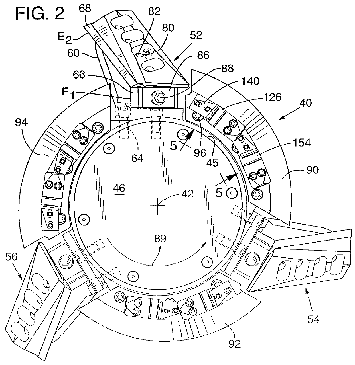
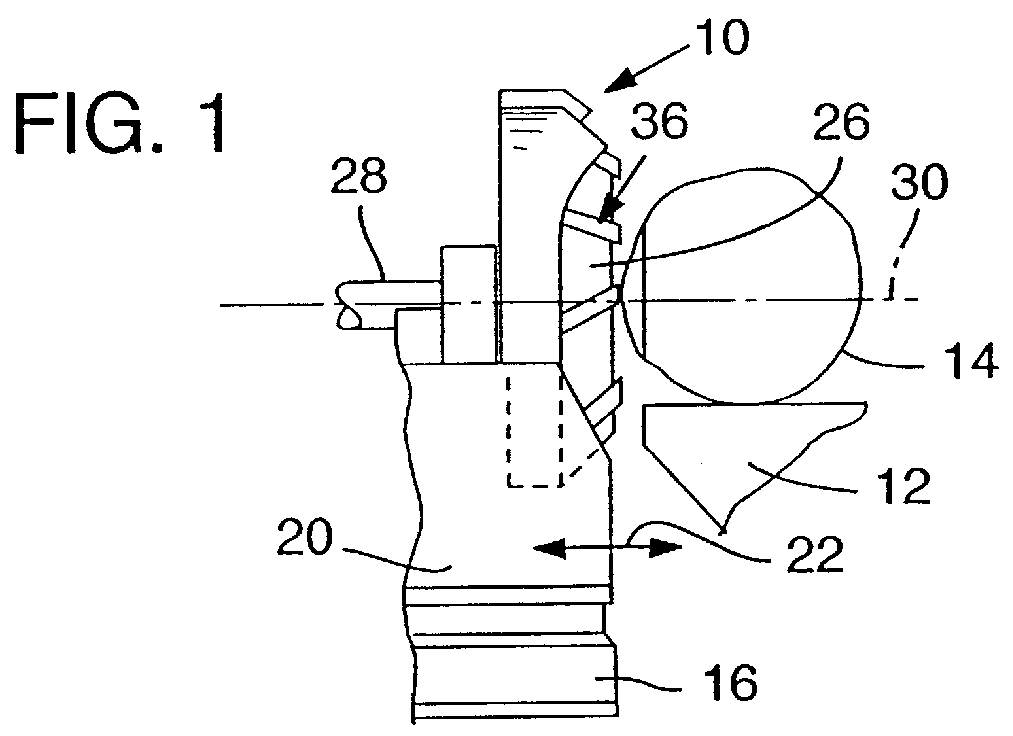
Referring now to the drawings, a log-slabbing chipper is illustrated in simplified form in FIG. 1 at 10. The chipper or woodworking machine includes a carriage 12 or log-supporting means, which mounts a log 14, with the log and carriage being movable in a direction extending longitudinally of the log (or toward and away from the viewer as the log and carriage are illustrated in FIG. 1).

Supported to one side of the carriage, on a frame 16 suitably mounted on the ground, is a stand 20. The stand is mounted for movement in the lineal path along the frame toward and away from the log, or in the direction indicated by the arrow 22 in FIG. 1.

Rotatably supported on stand 20 is a power-driven chipping head 26. The chipping head is rotated under power, about an axis 30, by suitable means, such as belts, or a motor connected to shaft 28.

Distributed about axis 30 on the chipping head are multiple knife structures given the reference numeral 36. With the chipping head rotated under power, and w...


PUM

PropertyMeasurementUnit
Angleaaaaaaaaaa
Speedaaaaaaaaaa
Perimeteraaaaaaaaaa

Abstract

A rotary chipping head with multiple knife structures distributed about its periphery. Each knife structure includes an end-located chipping knife with a cutting edge movable in a plane disposed perpendicular to the axis of rotation of the chipping head. End-located facing knives are interspersed with the knife structures for producing a smooth face in the work being processed. Anvils preceding the facing knives produce compression in the work being processed. Detachable facing elements mount the facing knives and the anvils.

Description

BACKGROUND AND SUMMARY OF THE INVENTIONThis invention relates to woodworking machines, as exemplified by apparatus known in the industry as a log-slabbing chipper.A log-slabbing chipper typically includes a power-rotated head disposed to one side of a support for a log. The head supports knife structure on its periphery which operates on rotation of the head to chip-off wood material on a log with relative movement of the head with respect to a log thereadjacent. The knife structures on the chipper head are rotated against a side of the log to produce the chipping action. Each knife structure includes one edge portion (a chip-cutting edge portion) which extends axially along the power-rotated head which functions to cut off the major portion of the chips produced by the apparatus as the edge portion is rotated and moved along a side of a log. In a typical log-slabbing chipper, this edge portion extends axially and also slopes inwardly toward the axis of the head, so that the edge po...

Claims


Application Information

Patent Timeline
IPC IPC(8): B27B33/00B27B33/20B27G13/08B27L11/00
CPCB27B33/20B27L11/007Y10T407/227Y10T407/1932Y10T407/2282
Inventor TOOGOOD, WILLIAM C.
Owner KEY KNIFE
Why Eureka
Try Eureka