Moving image signal coding apparatus and coded signal decoding apparatus

a signal coding and moving image technology, applied in the direction of color television with bandwidth reduction, television system, instruments, etc., can solve the problems of image quality deterioration, loss of cell units, and large loss, and achieve the effect of achieving the effect of practical application

Inactive Publication Date: 2000-08-15
JVC KENWOOD CORP A CORP OF JAPAN
View PDF7 Cites 93 Cited by
  • Summary
  • Abstract
  • Description
  • Claims
  • Application Information

AI Technical Summary

Benefits of technology

As has been described above, a moving image coding apparatus and decoding apparatus of the present invention has advantageous effects in its practical application.

Problems solved by technology

When there is a coding error between the coding apparatus and its decoding apparatus during transfer or recording, normal demodulation does not occur and there is a deterioration in the image quality.
Coding errors result in cell loss in ATM (asynchronous transfer mode) circuits when they occur in normal circuits and recording media, and this loss in cell units becomes a "dropout".
However, coding errors in independent frames can only be compensated for spatially and so there the deterioration becomes large, and the image is influenced later.
Furthermore, the amount of data for independent frames is larger than that for prediction frames and so when there are ten independent frames at once, the amount of data is about 40% of the overall amount of data, and the influence of coding errors becomes serious.

Method used


Image

  • Moving image signal coding apparatus and coded signal decoding apparatus
  • Moving image signal coding apparatus and coded signal decoding apparatus
  • Moving image signal coding apparatus and coded signal decoding apparatus

Examples


first embodiment

First is a description of the coding apparatus of the present invention.

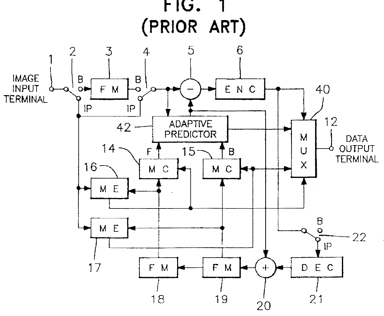
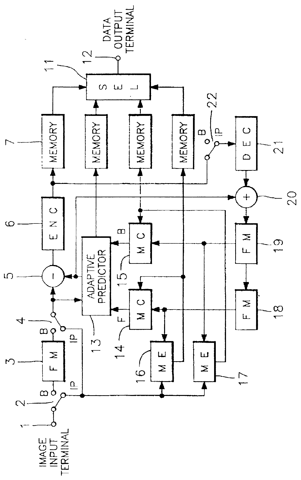
FIG. 3 is a block diagram showing an outline configuration of a moving image signal coding apparatus according to the first embodiment of the present invention. Those portions which correspond to portions of the coding apparatus of FIG. 1 are shown with corresponding numerals.

In FIG. 3, the coding processing is fundamentally the same, with the operation of the changeover switches 2, 4 and 22, the predictive subtracter 5, the intraframe encoder 6, the intraframe decoder 21, the frame memories 18 and 19, the motion compensators 14 and 15, and the motion vector detectors 16 and 17 being the same (as shown by the dots and the like where there is coding in block units).

This coding apparatus differs from the conventional transfer method (FIG. 2) for each of the information of the DCT information which is the output of the intraframe encoder 6, the prediction mode information (MODE) which is the output of the adaptive ...

second embodiment

the present invention is applicable to the apparatus "High-efficiency Coding Apparatus and Decoding Apparatus," disclosed in U.S. Ser. No. 07 / 873,949 filed on Apr. 24, 1992, the inventor of which is the inventor of the invention of the present application.

This embodiment has an improved coding efficiency while at the same time maintaining frame independence, and therefore even uses the inter-frame correlation for I-frames, and performs inter-frame image addition at the decoding apparatus, so that the coding method basically enables the image quality to be maintained even if the quantization is rough.

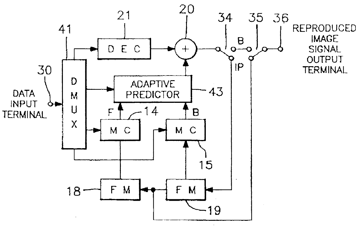
The difference with the first embodiment is the decoding apparatus, the configuration of which is shown in FIG. 5. The input data is coded by the coding apparatus shown in FIG. 3. The difference between the decoding apparatus of FIG. 5 and that of FIG. 4 is that there is a matching decider 32 which decides the matching of two images. More specifically, the configuration is such that the ...


PUM


Abstract

A coding apparatus which codes moving image signals into block units, is configured from a signal processing element which performs motion compensation for moving image signals for over a plural number of frames or fields and codes inter-image signals, and a transfer element which recombines coded information for each block coded by said processing element, into macroblock units which are a plural number of block units of each type of coded information, and transfers them. In addition, a decoding apparatus for moving image signals which have been coded in block units is configured from a detector element which detects transfer code errors for each type of coded information, and a processing element which performs motion compensation and inter-image processing of the coded information using only correct frames which do not include transfer code errors, and without using frames which have transfer code errors, by changing a method of inter-frame processing for motion compensation in accordance with the transfer coding errors in the coded information which has been detected for each type.

Description

BACKGROUND OF THE INVENTIONThe present invention relates to high-efficiency coding and decoding apparatus which are used in recording, transfer and display apparatus which perform digital signal processing, and which perform efficient coding and decoding, and in particular, to coding and decoding apparatus which perform inter-image processing of moving image signals have small deterioration of image quality even when there are transmission errors.High-efficiency coding of moving image signals (moving images) can involve interframe predictive coding which uses the correlation between frames of image signals and uses a frame for which coding has been performed, to predict and code only the prediction error. In recent years, motion compensation predictive coding has become the general method used for prediction in accordance with motion of an image.On the other hand, in coding in which a storage media is the object, intraframe independent coding is performed without interframe predicti...

Claims


Application Information

Patent Timeline
Patent Type & Authority Patents(United States)
IPC IPC(8): H04N7/46H04N19/102H04N19/50H04N19/159H04N19/174H04N19/423H04N19/46H04N19/503H04N19/51H04N19/61H04N19/625H04N19/65H04N19/67H04N19/70H04N19/85H04N19/89H04N19/895
CPCH04N19/51H04N19/89H04N19/517H04N19/577
Inventor SUGIYAMA, KENJI
Owner JVC KENWOOD CORP A CORP OF JAPAN
Why Eureka
Try Eureka