Optical fiber ferrule connector having enhanced provisions for tuning

Inactive Publication Date: 2001-03-06
LUCENT TECH INC
View PDF15 Cites 72 Cited by
  • Summary
  • Abstract
  • Description
  • Claims
  • Application Information

AI Technical Summary

Benefits of technology

The foregoing problems of the prior art have been overcome by the connector of this invention. An optical fiber connector comprises a ferrule assembly including a ferrule portion having a passageway for an optical fiber, and a plug frame in which is disposed the ferrule assembly. In a preferred embodiment, the plug frame includes inwardly radially projecting, circumferentially spaced splines. The ferrule assembly is disposed in the plug frame such that grooves formed between segmented portions of said collar receive splines of the plug frame therebetween to prevent relative rotation between the ferrule assembly and the plug frame. The ferrule assembly includes a barrel portion which projects toward a latching end portion of the plug frame. A ferrule projects

Problems solved by technology

Some prior art optical fiber connectors contain one or more precision-machined parts and therefore are relatively costly items.
Whereas this may be acceptable for some applications, in other cases the cost of such prior art connectors might constitute a significant fraction of the total installation cost.
Because it is very difficult to control the eccentricity of the optical fiber core in the ferrule in which it is terminated, it i

Method used


Image

  • Optical fiber ferrule connector having enhanced provisions for tuning
  • Optical fiber ferrule connector having enhanced provisions for tuning
  • Optical fiber ferrule connector having enhanced provisions for tuning

Examples


Example

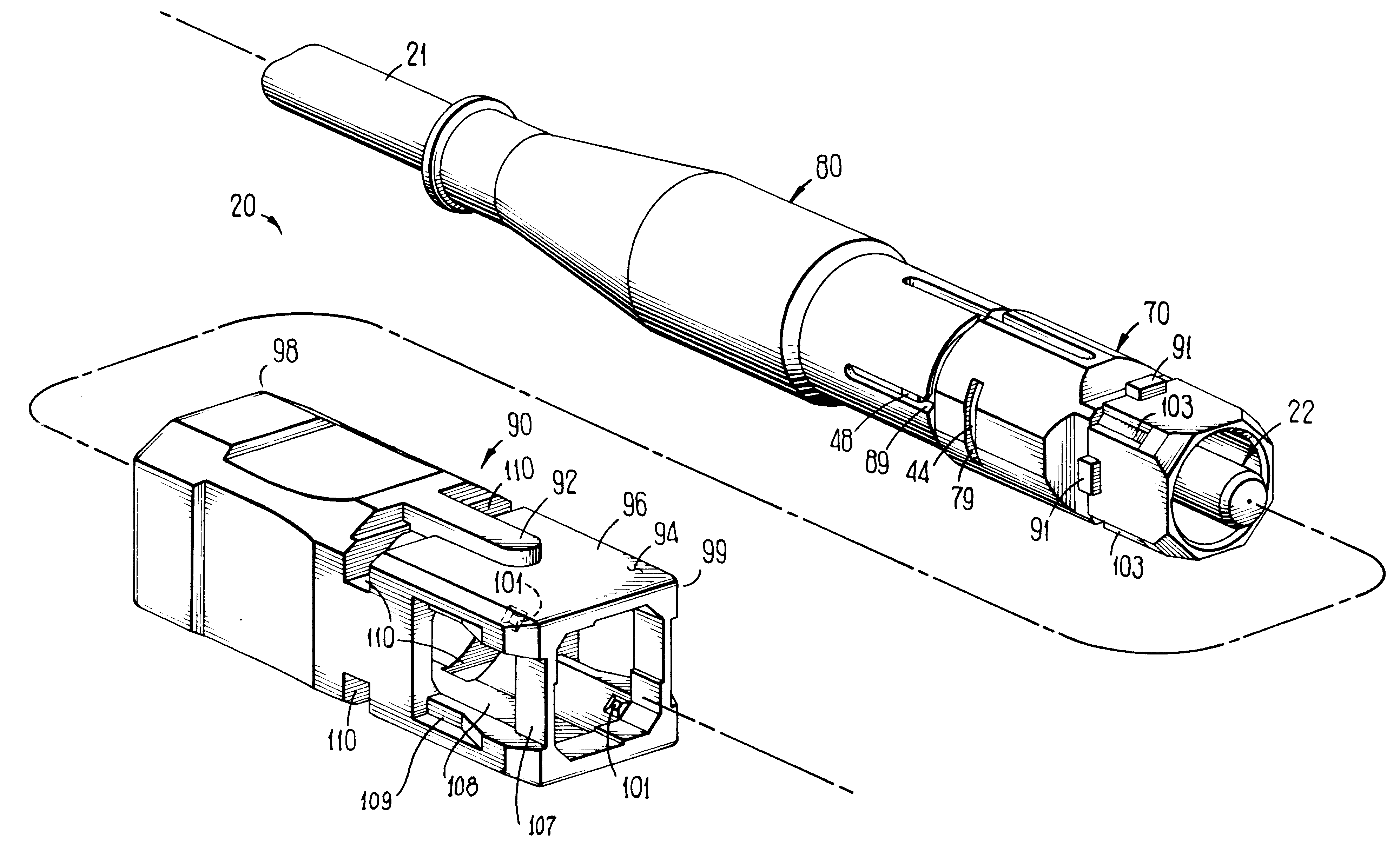
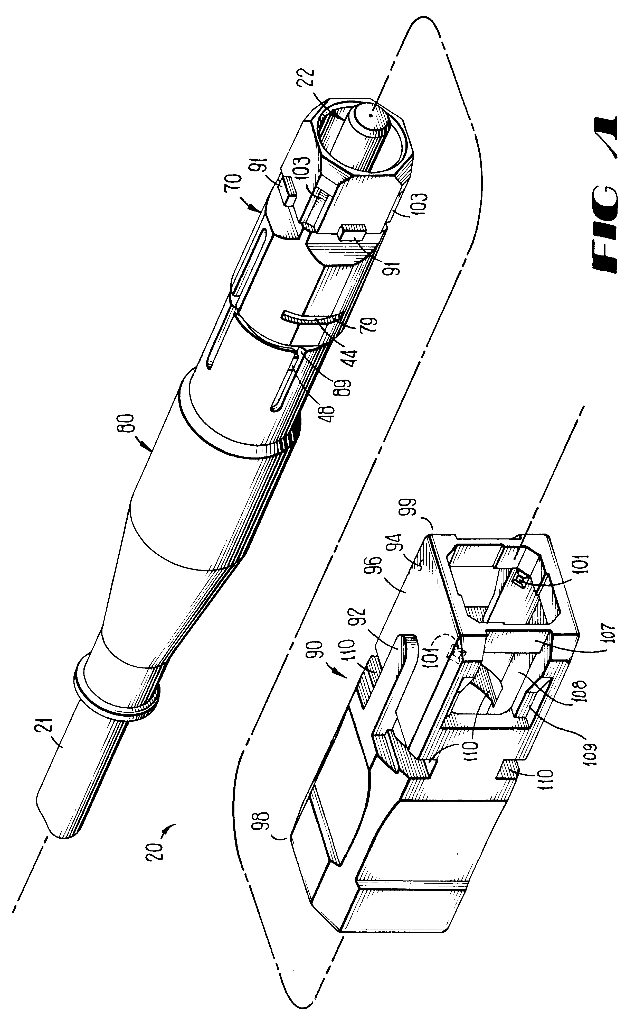
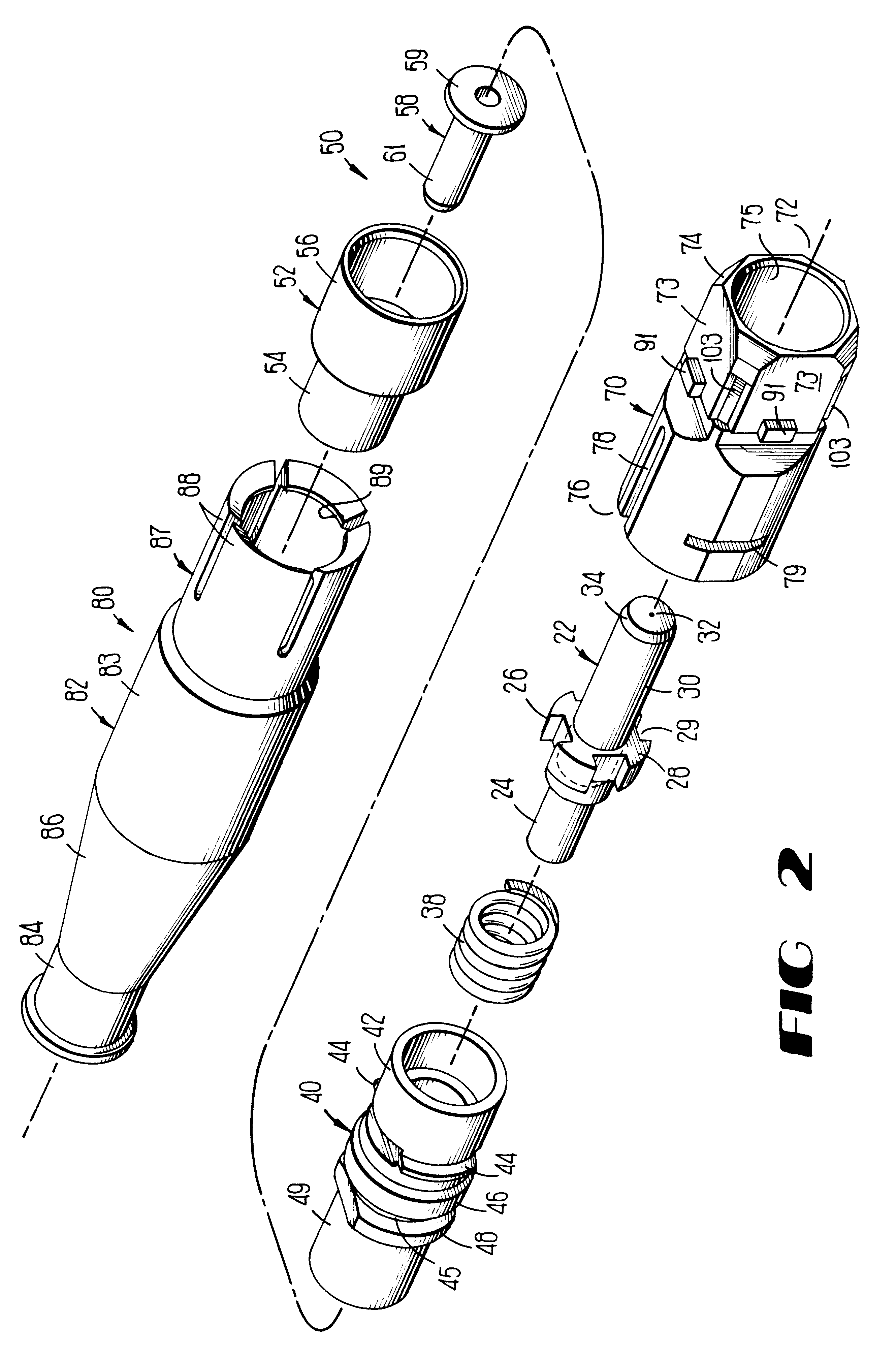
Referring now to FIG. 1, there is shown a connector which is designated generally by the numeral 20 which is adapted to terminate an optical fiber cable 21. The connector 20 comprises a ferrule assembly which is designated generally by the numeral 22. The ferrule assembly includes a barrel 24 (see also FIG. 2) having a segmented collar 26 at one end thereof. For the purpose of antirotation the collar 26 is provided with segments 28-28 with a groove 29 formed between each adjacent two of the segments. Four segments 28-28 are preferred but more or less could be used. Extending from a cavity in an opposite side of the collar 26 is a ferrule 30 which is made of a ceramic material, for example, and which has an optical fiber receiving passageway 32 formed along a longitudinal centerline axis thereof. Further, a free end of the ferrule 30 has a beveled portion 34 which facilitates insertion of the ferrule into an alignment device. In order to facilitate the insertion of one end portion of...


PUM


Abstract

An optical connector (20) includes a ferrule assembly (22) which is adapted to be received in a plug frame (70). The ferrule assembly is held in the plug frame by a cable retention assembly (40) which is adapted to be secured to said plug frame. A leading end of the plug frame is symmetrical in an end cross-section which is normal to a longitudinal axis of the connector. After the ferrule assembly has been assembled to the plug frame, the direction of any eccentricity of the plug passageway or of an optical fiber terminated by the ferrule assembly is determined. Then the plug frame is assembled to a housing of a grip (90) such that the direction of eccentricity is aligned with a key (92) of the grip. The plug frame is capable of being assembled to the grip notwithstanding the rotational orientation of the plug frame with respect to the grip. An optical connection between optical fibers terminated by two connectors is made by inserting the grip of each of the two connectors into a coupling housing (100) so that the keys are aligned. Advantageously, portions of the connector may be factory assembled which facilitates field use of the connector to terminate optical fiber.

Description

TECHNICAL FIELDThis invention relates to an optical fiber ferrule connector having enhanced provisions for tuning. More particularly, the invention relates to an SC connector which includes enhanced provisions for tuning eccentricity of an optical fiber core or fiber-receiving passageway in the ferrule.BACKGROUND OF THE INVENTIONOptical fiber connectors and splices are an essential part of optical fiber communications systems. Connectors may be used to join lengths of optical fiber into longer lengths, or to connect optical fiber to active devices such as radiation sources, detectors, or repeaters, or to passive devices such as switches or attenuators.An optical fiber connector must meet at least two requirements. It must couple or join two optical fibers with minimum insertion loss. Secondly, it must provide mechanical stability and protection to the junction between the optical fibers in the working environment. Achieving low insertion loss in coupling two optical fibers in genera...

Claims


Application Information

Patent Timeline
IPC IPC(8): G02B6/38G02B6/36
CPCG02B6/3821G02B6/3831G02B6/3843G02B6/3851G02B6/3874G02B6/3893G02B6/3871G02B6/3888H01R11/28H01R13/56H01R13/514
Inventor STEPHENSON, DANIEL LEESUBH, NAIF TALEBTRAVIESO, RUBEN
Owner LUCENT TECH INC
Why Eureka
Try Eureka