Luer-receiving medical valve and fluid transfer method

a technology of medical valves and valves, which is applied in the direction of catheters, packaged goods, foodstuffs, etc., can solve the problems of not working, blunt, and well known, and achieve the effect of reducing overall cost, reducing the opening through slit, and maintaining the sterility of the tapered end

Inactive Publication Date: 2001-09-04
LYNN LAWRENCE A
View PDF62 Cites 89 Cited by
  • Summary
  • Abstract
  • Description
  • Claims
  • Application Information

AI Technical Summary

Benefits of technology

In the preferred embodiment, the projecting portions progressively lengthen to define a progressively decreasing distance between the projecting members so that the projecting members are closer to one another adjacent the main bore than adjacent the proximal cylindrical portion of the secondary bore. This effectuates a progressive enlargement of the opening through slit of the elastomeric septum piston when the elastomeric septum piston is fully advanced into the proximal portion of the secondary bore. Furthermore, after removal of the luer, as the elastomeric septum piston retracts away from the distal compressing portion toward the proximal portion, the slit progressively closes from its proximal extent toward its distal extent, thereby expressing fluid toward the main bore rather than toward the proximal opening of the secondary bore. This reduces the chance of blood or fluid refluxing out of the septum piston into the environment or into the secondary bore when luer taper cannula is withdrawn from the secondary bore. The branch of the main conduit can be aligned directly with or perpendicular to the main conduit or can be at an oblique or acute angle with the main conduit. The main conduit is generally discussed below as integral with the valve, but the main conduit may be a separate piece and sold separately, and may be joined with the branch or the aligned secondary bore by a threadable member as ,for example, joining a conventional heparin well or prn adapter to a catheter, stopcock, or IV tubing system. The branch preferably includes at least one external thread or thread receiver for receiving an internal female threading member to allow a secure threaded connection with a conventional luer-lock type connector of the type commonly used with conventional syringes or intravenous tubing systems. The use of this luer-activated valve in association with IV piggyback administration generally would require the recapping of the luer taper after use so that the luer taper remains sterile between IV piggyback mediation administrations. My U.S. Pat. No. 5,167,643 (the disclosure of which is hereby incorporated by reference as if completely disclosed herein) describes a Docking Station for receiving a blunt cannula such as a tapered luer end to maintain the sterility of the tapered end. The present invention includes the secondary tubing system having a docking station intended for use with a conventional luer taper cannula of the slip tip or luer lock type. This station utilizes a simple membranous cover since the primary function of the cover is to cover and seal the luer within the station, as discussed in the previous patent. The new protection station may include...

Problems solved by technology

The risk of needlestick injury and the expense associated with accessory cannulae, whether blunt or sharp, are well known.
Such a system will not work with a conventional luer lock system since the male taper extends centrally adjacent the luer lock threading member and therefore, it would not be possible to compress the septum piston within the luer-lock threads in such a system without inserting the male member itself into th...

Method used


Image

  • Luer-receiving medical valve and fluid transfer method
  • Luer-receiving medical valve and fluid transfer method
  • Luer-receiving medical valve and fluid transfer method

Examples


Embodiment Construction

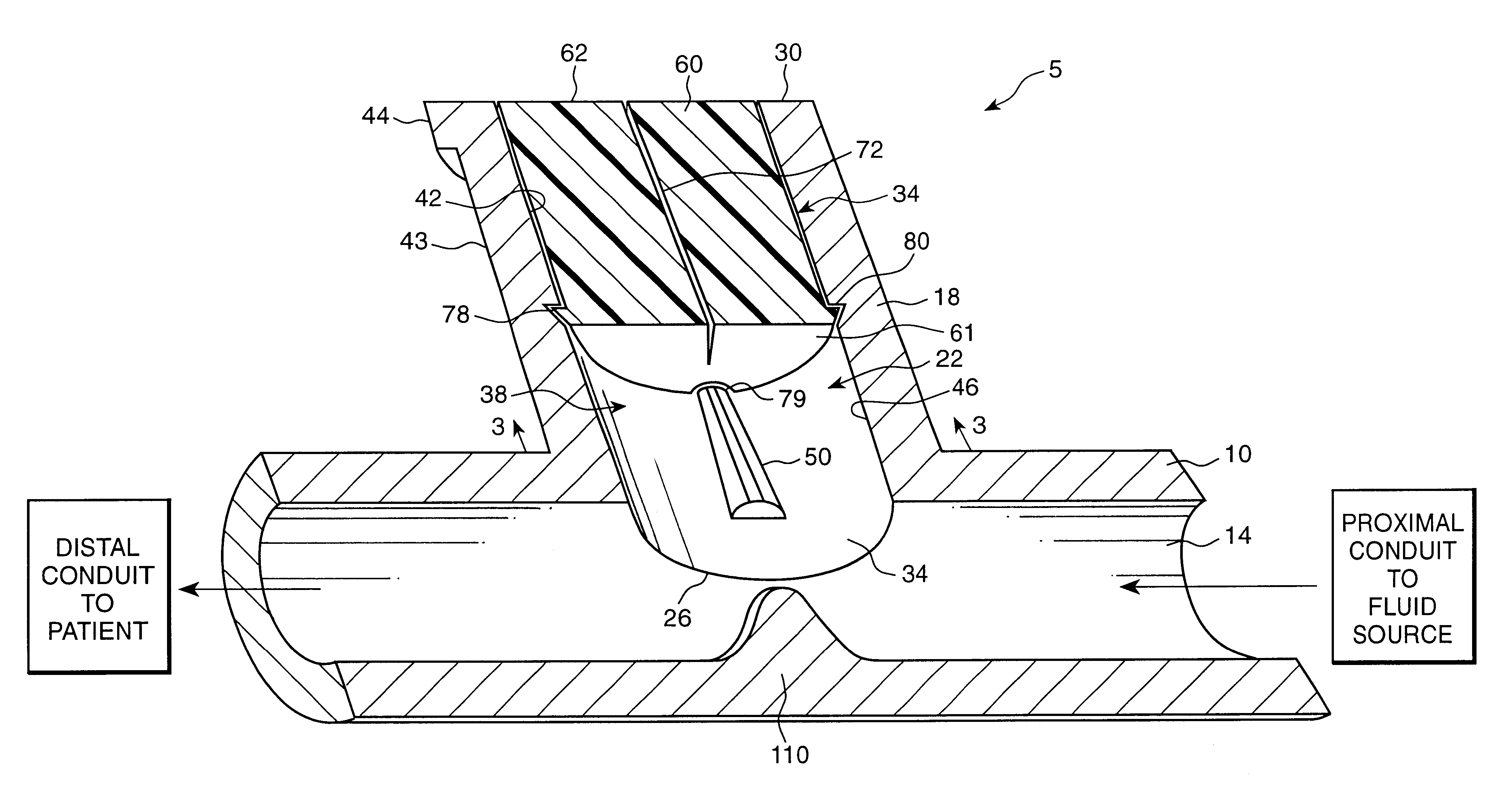
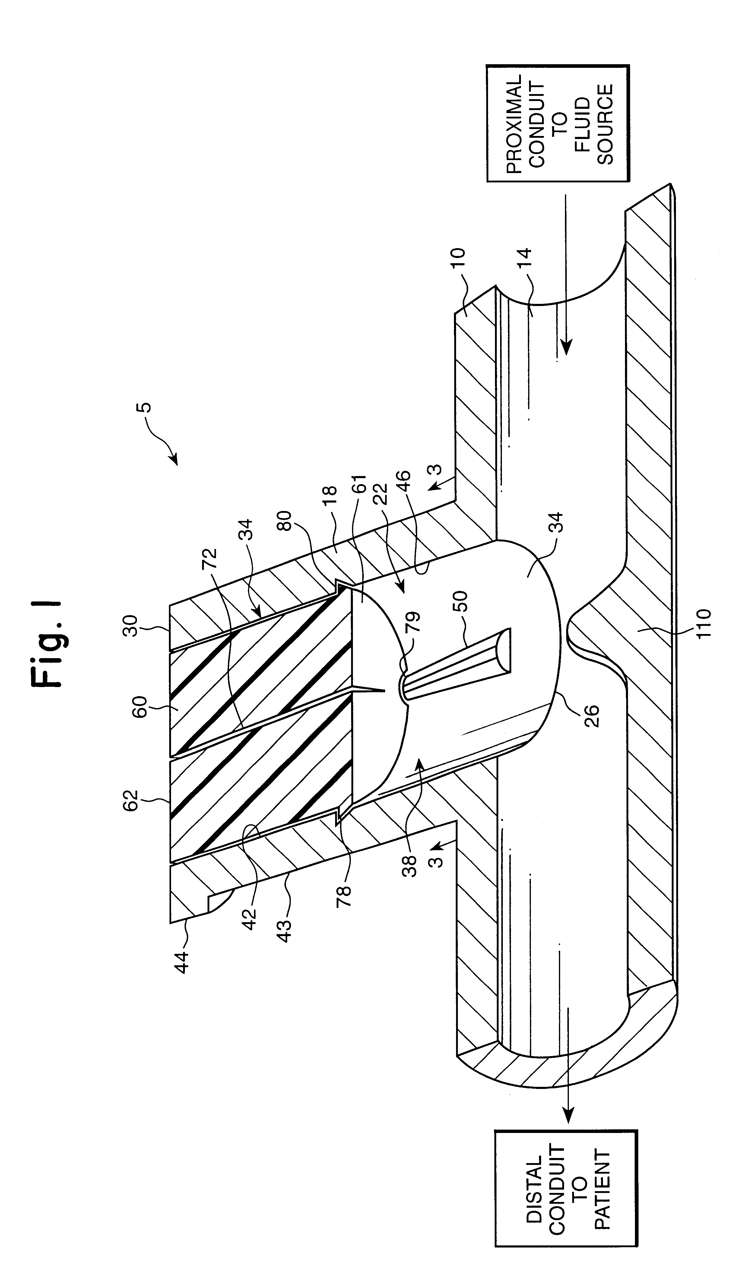
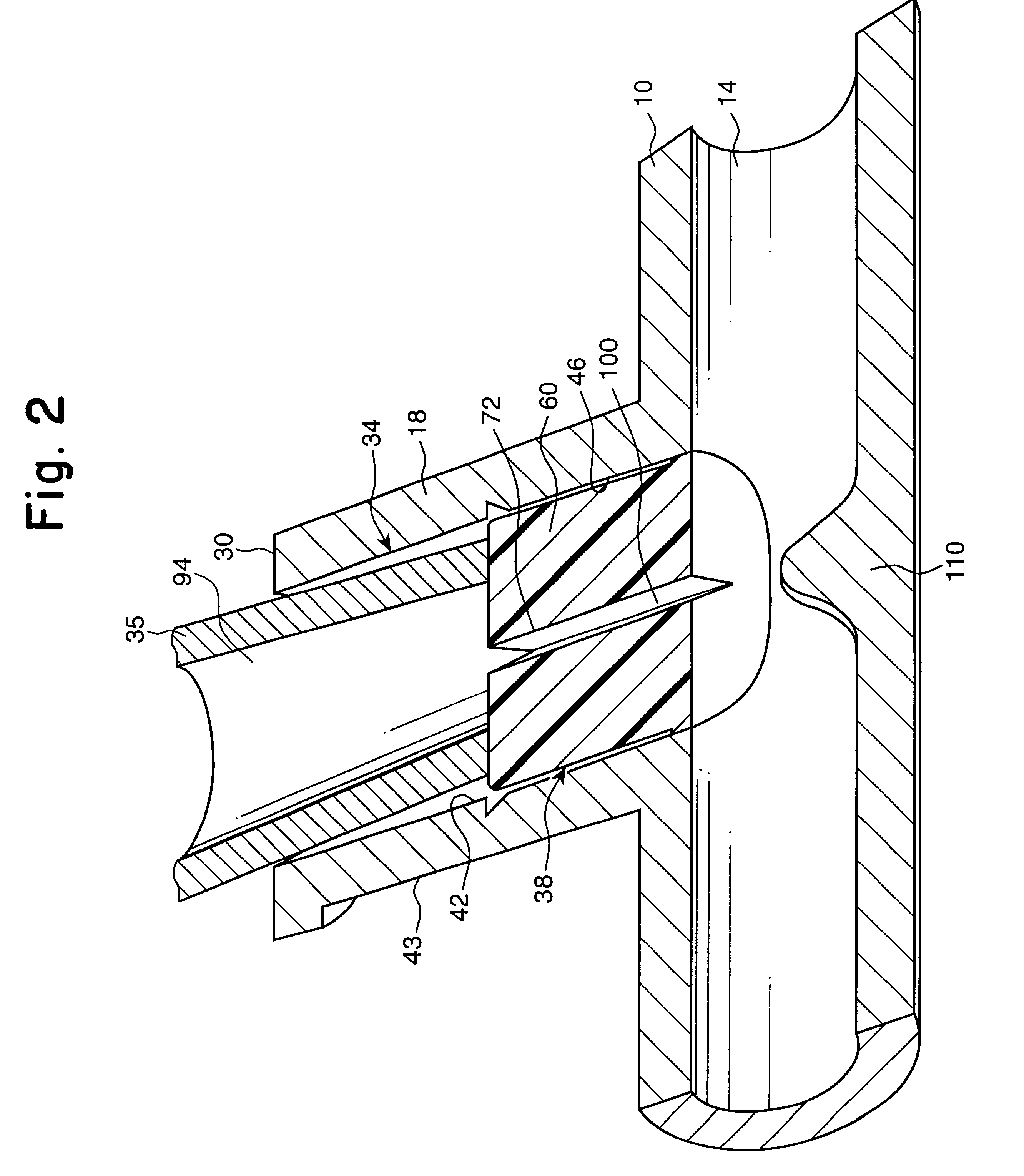
The luer tapered cannula receiving valve 5 (FIG. 1) includes a main conduit housing 10 having a main bore 14 and a secondary branch or cylinder 18 having a secondary bore 22. The cylinder 18 includes a distal end 26 adjacent the main bore 10 and a proximal end 30. The cylinder 18 further includes a cylindrical proximal bore portion 34 sized to sealingly receive a conventional tapered luer male cannula 35 (as shown in FIG. 2) and distal bore portion 38. The proximal bore portion 34 is defined by inner cylindrical walls 42 and outer walls 43 and includes outer thread receiving post 44 adjacent the proximal end 30 (although complete outer threads may be provided). A distal bore portion 38 is defined by distal wall 46 having opposing projecting members 50 which effectively narrow the transverse width of the distal bore portion 38 along a longitudinal plane through the opposing projecting members 50 (as best shown in FIG. 3). A cylindrical elastomeric septum piston 60 having a distal end...


PUM


Abstract

A medical valve is provided that includes a housing having a main conduit and a branch extending from the main conduit and in fluid communication with it. The bore of the branch has an elastomeric septum piston disposed therewithin and at least a portion of the elastomeric septum piston is movable by either compression or by a longitudinal advancement along the secondary bore towards the bore of the main conduit. In one embodiment, the septum piston is cylindrical and includes a centrally positioned slit. The bore of the branch includes two opposing projecting members along a distal portion of the bore which effectively narrow the diameter of the bore. When the elastomeric member is pushed from a proximal position to a distal position, it is transversely compressed by the projecting members to open the slit and allow fluid passage. After removal of the longitudinal displacement force the septum piston retracts away from the distal portion back to the proximal portion.

Description

BACKGROUND AND SUMMARY OF THE INVENTIONThe risk of needlestick injury and the expense associated with accessory cannulae, whether blunt or sharp, are well known. Conventional intravenous tubing systems utilize tapering luer male cannula connectors, often within an associated surrounding threadable member defining a luer-lock connector commonly used for achieving tight, sustained connections. A bare luer taper cannula without the associated threadable member is commonly called a luer slip connector and is widely utilized for brief prn injections. Both of these luer systems are in wide use throughout conventional hospital systems and it would be preferable to develop a connecting valve system which receives and is activated by conventional luer slip tapers or luer lock tapers so that incorporation into existing hospital systems is rapid and associated with minimal cost. It would be advantageous for such systems to avoid deadspace so that the surface could be easily wiped with antisept...

Claims


Application Information

Patent Timeline
IPC IPC(8): A61M39/02A61M39/26A61M39/00A61M39/04A61M39/20A61M5/24A61J1/00A61J1/20A61M25/18
CPCA61J1/2096A61M39/02A61M39/045A61M39/20A61M39/26A61J1/201A61J1/2044A61J1/2058
Inventor LYNN, LAWRENCE A.
Owner LYNN LAWRENCE A
Why Eureka
Try Eureka