Ink jet print head

a printing head and jet technology, applied in the field of jet printing head, can solve the problems of reducing the quality of recording, affecting the printing, and stopping the discharge, so as to avoid the effect of the subsequent discharge and shorten the damping time of the meniscus

Inactive Publication Date: 2001-11-27
NEC CORP
View PDF4 Cites 0 Cited by
  • Summary
  • Abstract
  • Description
  • Claims
  • Application Information

AI Technical Summary

Benefits of technology

According to the present invention, after an ink drop is discharged from an ink outlet by grown bubbles, the projection of a meniscus at ink refill is kept small by optimizing the channel resistance value of an ink supply path.
Therefore, the periodic damping time of the meniscus becomes short, and the unfavorable effect to be caused at the subsequent discharge is avoided.
Moreover, in the case in which the sectional area of the ink outlet is set large within the predeter

Problems solved by technology

Such satellites adversely affect the printing.
This causes an undesirable deformation of an ink drop and an undesirable development of low-speed satellites, resulting in a reduced quality of recording.
Further, some volume of ink may flood over a surface area around the ink outlet 38, causing an ink drop to be di

Method used


Image

  • Ink jet print head
  • Ink jet print head
  • Ink jet print head

Examples


Embodiment Construction

Detailed below is a preferred embodiment of the present invention, with reference to FIGS. 4 to 11. Like members are designated by like reference characters.

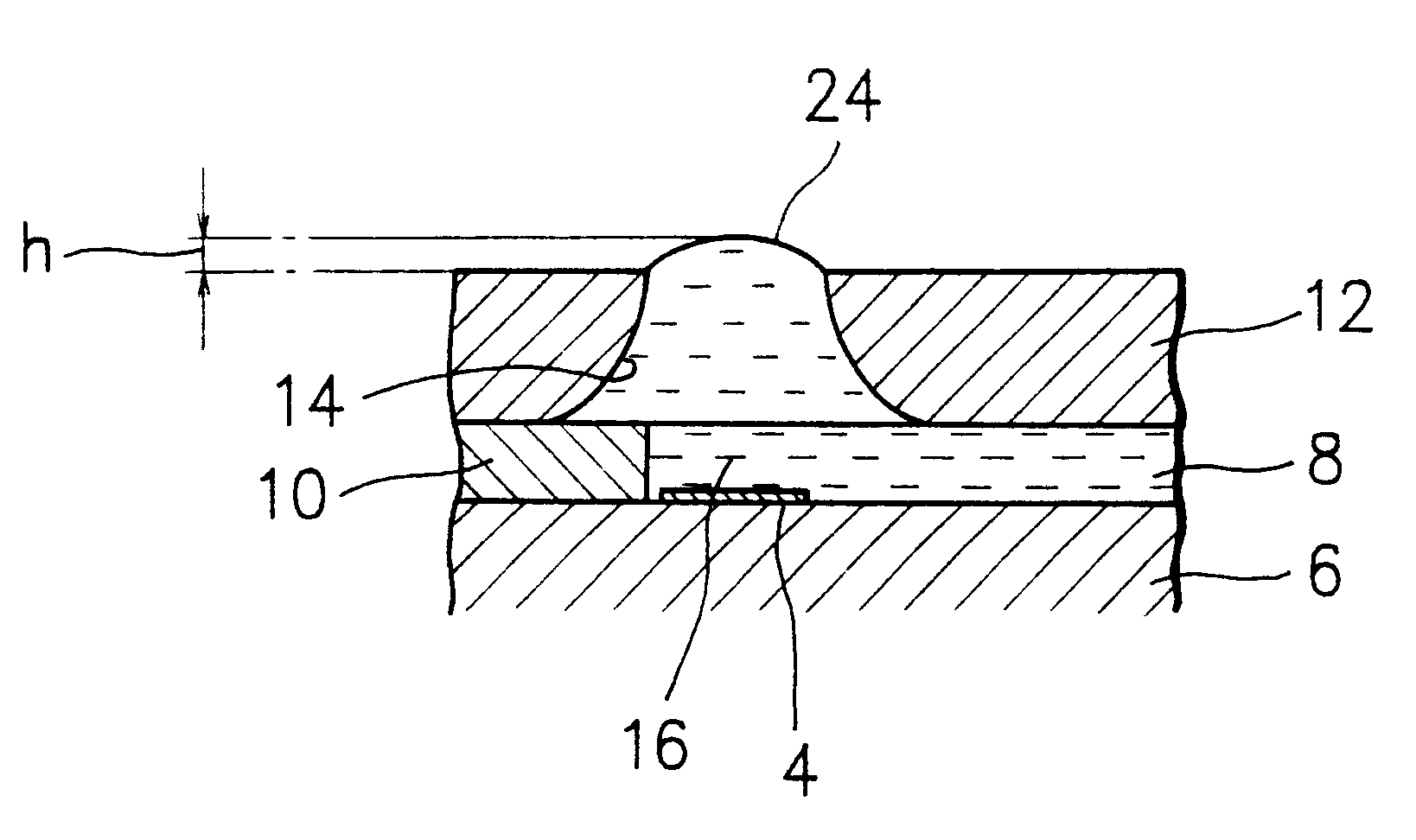
Referring now to FIG. 4, an ink jet print head 1 according to an embodiment of the invention comprises a substrate 6 formed with a plurality of heating resistors (hereafter collectively "heating resistor") 4 and a central recess or groove 6a used as an ink pool or trunk path. An ink path defining resin sheet member 10 defines a plurality of channels as branched ink supply paths (hereafter collectively "ink supply path") each including a heating zone. An orifice plate 12 is formed with a plurality of orifices or nozzles as ink outlets 14 (hereafter collectively "ink outlet").

FIG. 5 shows a cross sectional view of a nozzle of an ink jet print head (multi-nozzle) identical to the print head 1. FIG. 6 shows a plan view of Ie ink jet print head with an orifice plate removed.

An ink jet print head 2 is provided with a substrate 6, a he...


PUM


Abstract

An ink jet print head comprises a substrate formed with a heating resistor, an ink path defining member for defining an ink supply path, and an orifice plate, and in the orifice plate, there is formed an ink outlet at the position opposing the heating resistor. Further, a heating zone surrounding the heating resistor is formed at the position corresponding to the heating resistor of the ink supply path. The channel resistance of the ink supply path is set so that a relationship is established between a quantity q of the discharged ink drop, a sectional area A of the ink outlet, and a maximal projection h that a meniscus of the ink has when it projects from the ink outlet after it has restored the exit level from a retreat position it had after the drop of the ink had been discharged such that <DEL-S DATE="20011127" ID="DEL-S-00001">0<h<0.3q/A<DEL-E ID="DEL-S-00001"> <INS-S DATE="20011127" ID="INS-S-00001">0<h<0.25q/A<INS-E ID="INS-S-00001">. Consequently, there is obtained a high-speed printing of high quality without dispersion.

Description

BACKGROUND OF THE INVENTIONThe present invention relates to an ink jet print head for discharging ink drops from ink outlets by use of thermal energy.Description of the Related ArtRecently, in contrast with the wire dot printing methods, non-impact recording method is attracting interest became the recording noise level is negligible. In particular, an ink et recording method is attractive as it permits high-speed recording on ordinary paper without the need of a deposition treatment on the paper side. In the field, therefore, aiming at an optimal ink discharge performance, various approaches have been made, with associated implementations.In the ink jet recording method, a recording is effected with discharged droplets of recording liquid, called "ink" deposited on a recordable material. This method is categorized into several systems according to the manner in which the drops of recording liquid are formed.FIG. 1 illustrates a bubble jet recording system as a conventional example....

Claims


Application Information

Patent Timeline
IPC IPC(8): B41J2/14B41J2/05B41J2/01
CPCB41J2/01B41J2/1404B41J2/1433B41J2002/14387B41J2002/14475B41J2202/03B41J2202/11
Inventor UTMATSU, RYOSUKISUETSUGU, JUNICHISHIMA, KAZUOYAMADA, MINORUHAGIHARA, YOSHIHIROFUJISAWA, JUNICHI
Owner NEC CORP
Why Eureka
Try Eureka