Planar direct drive unit comprising a position measuring system

a technology of position measuring system and planar motor, which is applied in the direction of dynamo-electric machines, instruments, and element comparison, etc., can solve the problems of limiting the positioning accuracy of the planar motor, unable to tolerate errors of this type, and unable to achieve the effect of reducing the number of adjustment operations, and increasing the accuracy

Inactive Publication Date: 2009-02-10
INA DRIVES & MECHATRONICS
View PDF8 Cites 0 Cited by
  • Summary
  • Abstract
  • Description
  • Claims
  • Application Information

AI Technical Summary

Benefits of technology

[0017]It should be pointed out that the use in accordance with the invention of the above-explained position measuring system in planar direct drives allows greater accuracy than, for example, with the use of Hall sensor measuring systems or with automatic control of the direct drives in microstep operation. Compared to position determination by camera-supported image analysis, which is used in some cases, the measuring system used here also has considerable advantages, since significantly less data must be processed, so that the direct drive can be automatically controlled more quickly.
[0018]Another important aspect of the invention is that the passive unit itself or the running surface formed on it is no longer integrated in the measuring sequence. This also eliminates the adjustment ope...

Problems solved by technology

However, this also limits the positioning accuracy of the planar motor, which depends directly on the tooth pitch and its accuracy.
Another problem is that the positioning accuracy also depends on environmental conditions, especially the temperature of the passive unit.
If direct drives of this type are to be used for positioning tasks with high accuracy requirements, errors of this type can no longer be tolerated.
Ongoing miniaturization in many technical fields requires rather an increase in positioning accuracy, which cannot be achieved with previously known integrated position measuring systems.
In this case, however, either large and heavy position measuring standards must be carried by the active unit, or coupling t...

Method used


Image

  • Planar direct drive unit comprising a position measuring system
  • Planar direct drive unit comprising a position measuring system
  • Planar direct drive unit comprising a position measuring system

Examples


Embodiment Construction

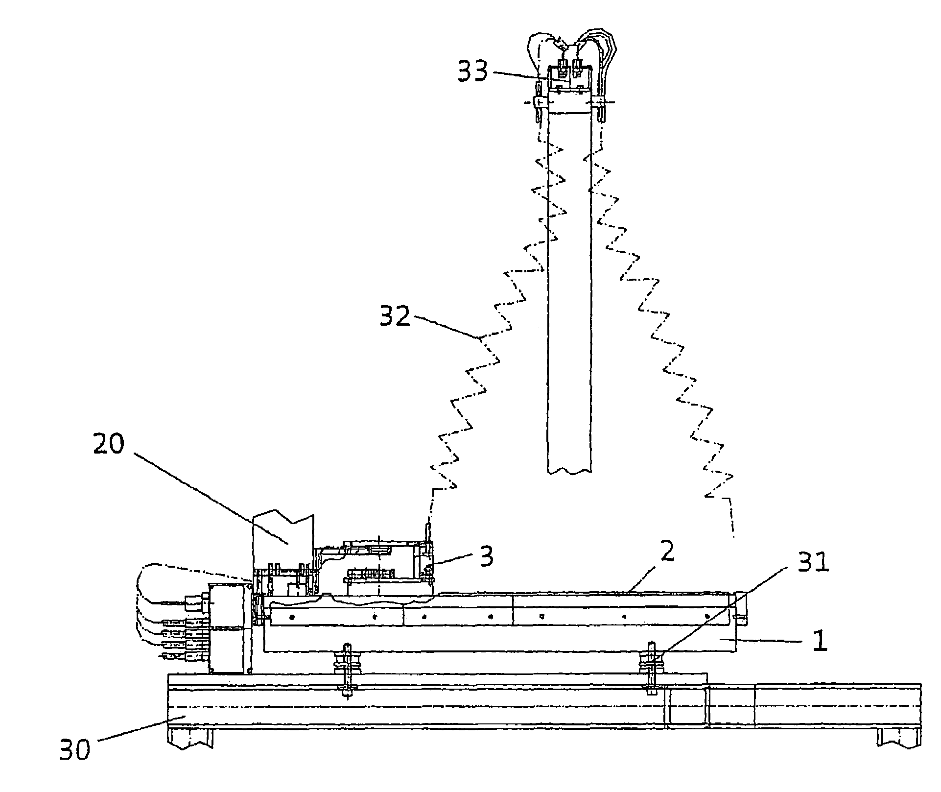
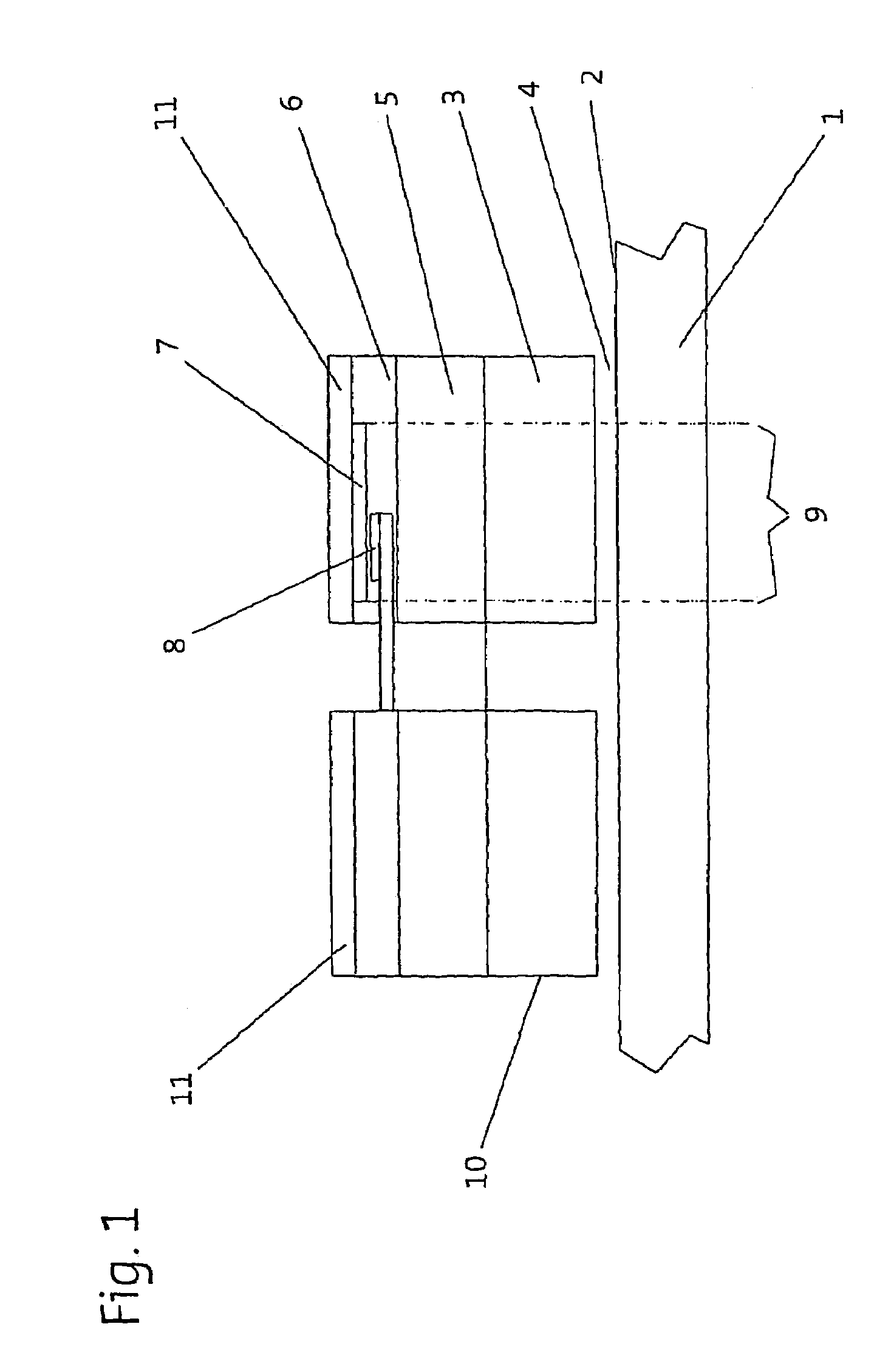
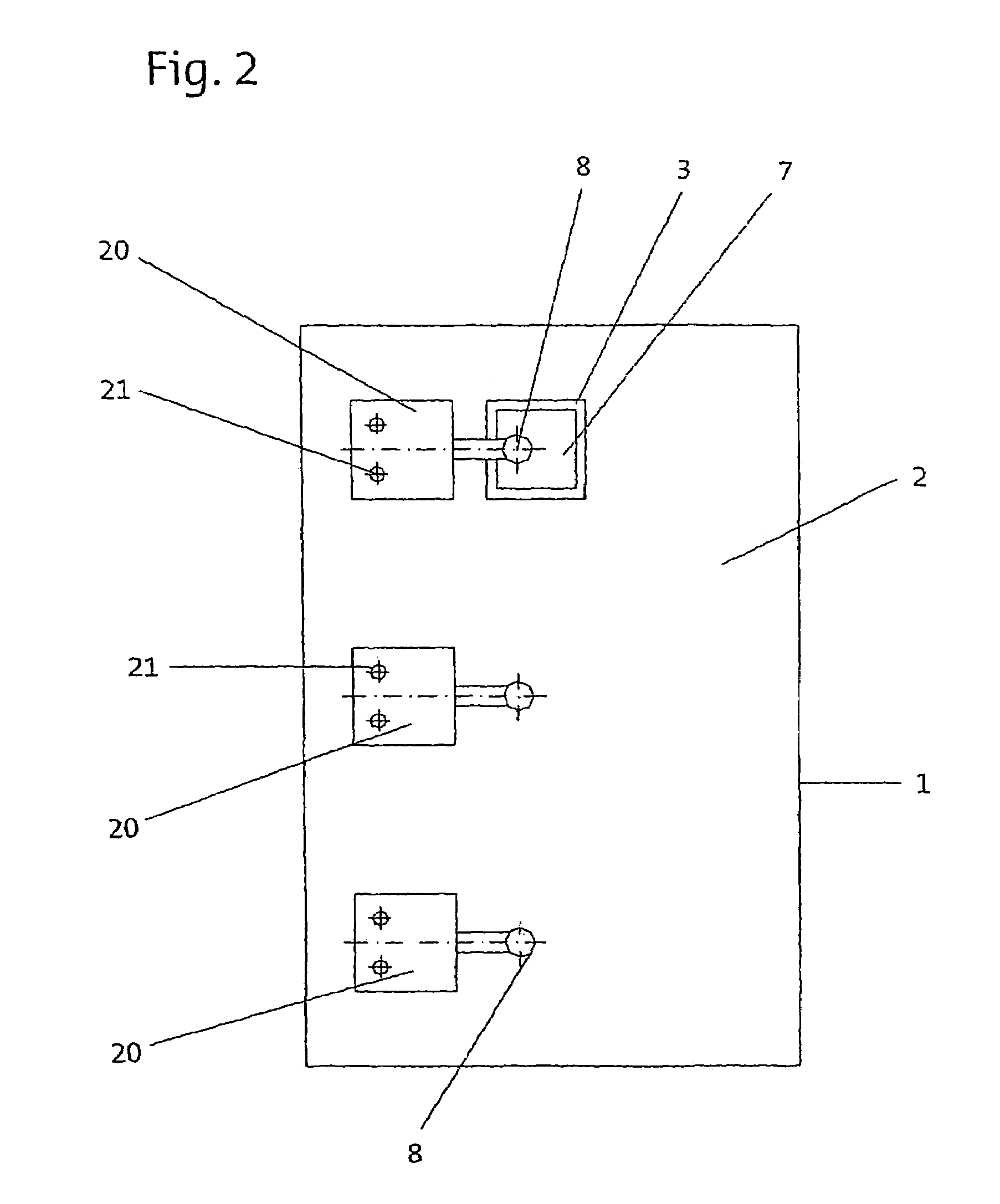
[0030]The planar direct drive shown in FIG. 1 comprises a passive unit 1, the upper side of which has a running surface 2. A tooth pitch, for example, which runs crosswise and consists of magnetizable teeth and nonmagnetizable tooth spaces, is formed on the running surface 2. Those skilled in the art are already familiar with the general design of direct drives of this type, so there is no need to provide a detailed description of how this planar motor works.

[0031]The direct drive also has a first active unit 3, which can be moved in at least two directions of motion on the running surface 2 when power is supplied by suitable means. To allow movement despite the force of magnetic attraction between the active unit 3 and the passive unit 1, a bearing unit is necessary, by which a bearing gap 4 is maintained during the operation of the direct drive. Air bearings (not shown) are suitable and preferred for this purpose. They produce an air gap between the running surface 2 and the activ...


PUM


Abstract

The invention relates to a planar direct drive unit comprising a passive unit (1), an active unit (3), a bearing unit, and a position measuring system that is provided with a material measure and a measuring sensor which scans the material measure and supplies a position signal. The inventive positioning measuring system encompasses a moved component (7) and a quasi stationary component (8), one of which is formed by the material measure while the other one is formed by the measuring sensor. Both components are disposed outside the bearing gap (4) and at a distance from the running surface (2).

Description

[0001]This is a National Phase application of International application No. PCT / EP2004 / 007042 filed Jun. 29, 2004, which claims priority from DE 10329931.9 filed Jul. 2, 2003 and DE 10357585.5 filed Dec. 8, 2003.BACKGROUND OF THE INVENTION[0002]The present invention concerns a planar direct drive (also known as a planar motor), which includes a position measuring system for controlling the travel of the rotor. Direct drives of this type have a passive unit with a planar running surface, in which magnetic flux regions are integrated. This passive unit constitutes the stator of the motor. In addition, there is at least one active unit (rotor) with coil systems for generating a variable magnetic flux. The active unit can move on the running surface of the passive unit. Furthermore, the direct drive has a bearing unit, which allows frictionless two-dimensional relative motion of the active and passive units.[0003]DE 195 13 325 A1 describes, for example, a Hall sensor position measuring ...

Claims


Application Information

Patent Timeline
IPC IPC(8): G05B1/06H02K29/06H02K41/03
CPCH02K41/03H02K29/06H02K2201/18
Inventor KEGELER, JORG
Owner INA DRIVES & MECHATRONICS
Why Eureka
Try Eureka