Mount bracket

a technology of mounting brackets and brackets, applied in the direction of shock absorbers, instruments, liquid fuel engines, etc., can solve the problems of unfavorable effects, heat dissipation, and a large increase in heat dissipation, so as to reduce the unfavorable effects

Active Publication Date: 2021-03-02
COOLER MASTER CO LTD
View PDF6 Cites 0 Cited by
  • Summary
  • Abstract
  • Description
  • Claims
  • Application Information

AI Technical Summary

Benefits of technology

[0005]The disclosure provides a mount bracket which is capable of solving the unfavorable effects on the electronic components in the electronic product in the prior art caused by the vibration caused by the fan motor.
[0009]According to the mount bracket as discussed above, with the help of the vibration-absorbing component disposed between the button plate and the frame or the vibration-absorbing sleeve covering the frame, the mount bracket not only can support the fan, but also can decrease the unfavorable effects caused by the vibration caused by a fan motor.

Problems solved by technology

As electronic products become more and more compact and complex, the requirement of heat dissipation largely increases, thus heat dissipation now is a key issue to consider in designing the electronic products.
However, during the operation of the fan, the vibration caused by the fan motor will be transmitted to other electronic components in the electronic product via the mount bracket, causing unfavorable effects to these electronic components.

Method used


Image

  • Mount bracket
  • Mount bracket
  • Mount bracket

Examples


first embodiment

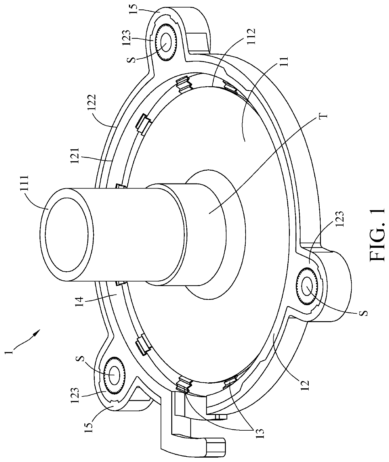
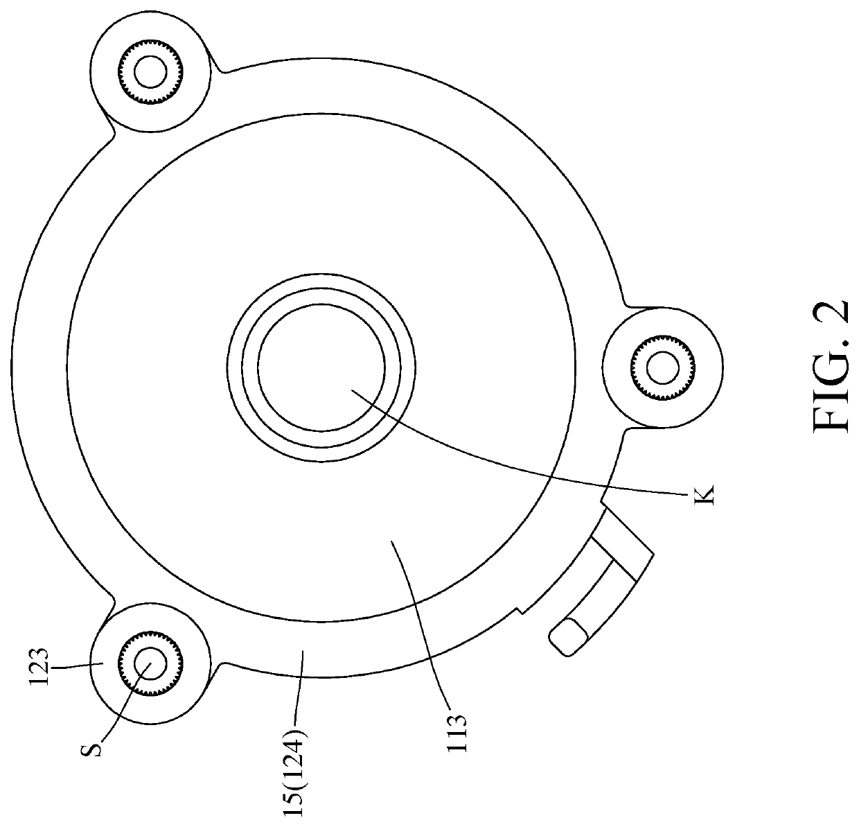
[0018]Please refer to FIG. 1 and FIG. 2. FIG. 1 is a perspective view of a mount bracket according to the disclosure. FIG. 2 is a schematic view of a button surface of the mount bracket in FIG. 1.

[0019]This embodiment provides a mount bracket 1 which is configured to be fixed with a fan. The mount bracket 1 includes a button plate 11, a frame 12 and a plurality of vibration-absorbing components 13. A motor mount 111 is mounted on the button plate 11. The frame 12 surrounds an outer side of the button plate 11, and the frame 12 has an inner lateral surface 121 and an outer lateral surface 122. A plurality of fixing structures 123 protrude from the outer lateral surface 122 of the frame 12. There is an annular gap 14 formed between the inner lateral surface 121 of the frame 12 and an outer lateral surface 112 of the button plate 11. The vibration-absorbing components 13 are spaced apart from one another and located in the annular gap 14. In more detail, each vibration-absorbing compon...

second embodiment

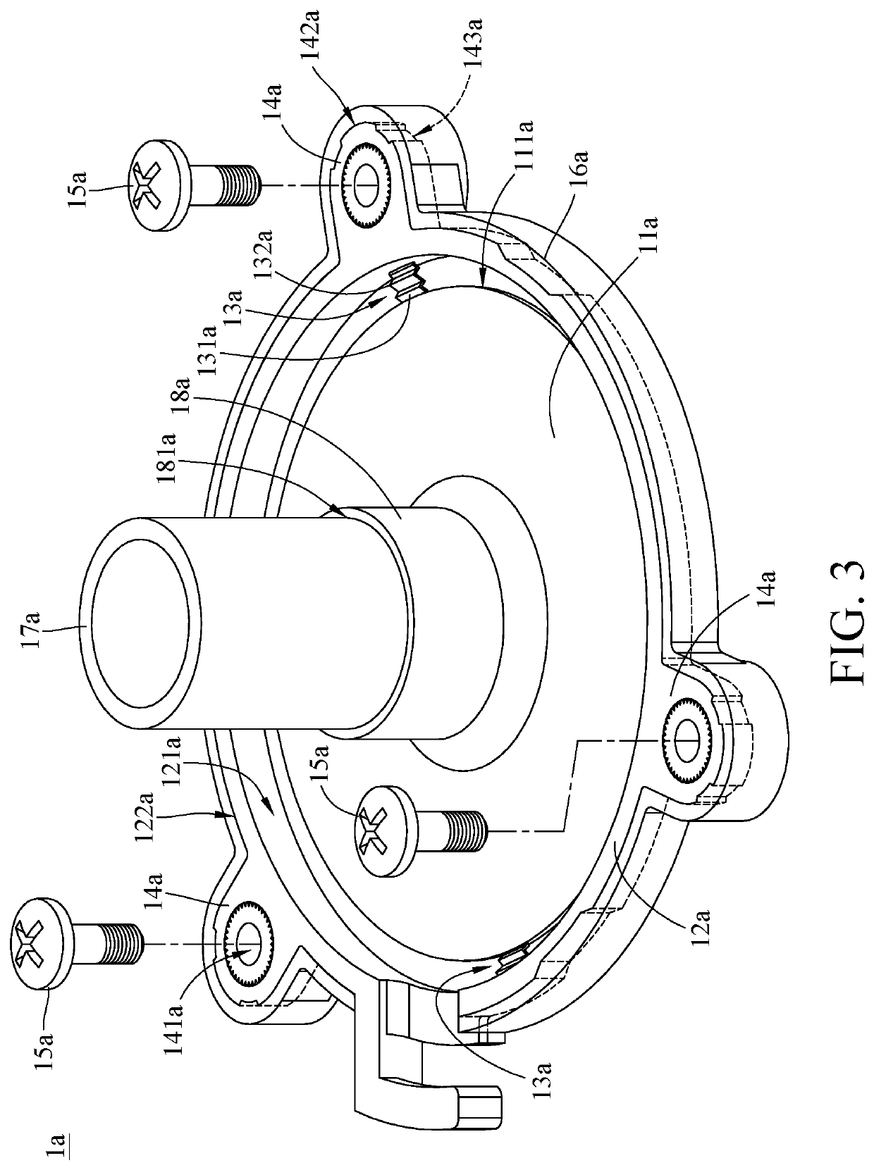
[0028]In the aforementioned embodiments, the quantity of the vibration-absorbing components 13 is larger than two, but the present disclosure is not limited thereto. Please refer to FIG. 3 and FIG. 4. FIG. 3 is a partial exploded view of a mount bracket according to the disclosure. FIG. 4 is a cross-sectional view of the mount bracket in FIG. 3;

[0029]This embodiment provides a mount bracket 1a. The mount bracket 1a includes a button plate 11a, a frame 12a, two vibration-absorbing components 13a, a plurality of fixing structures 14a, a plurality of fasteners 15a and a vibration-absorbing sleeve 16a.

[0030]The button plate 11a has an outer lateral surface 111a, and the frame 12a has an inner lateral surface 121a and an outer lateral surface 122a opposite to each other. The inner lateral surface 121a of the frame 12a faces the outer lateral surface 111a of the button plate 11a. The two vibration-absorbing components 13a are disposed between the inner lateral surface 121a of the frame 1...


PUM


Abstract

The disclosure provides a mount bracket which is configured for a fan. The mount bracket includes a button plate, a frame and a plurality of vibration-absorbing components. The button plate is mounted with a motor mount. The frame surrounds the button plate, and the frame has an inner lateral surface and an outer lateral surface. A plurality of fixing structures protrude from the outer lateral surface of the frame. The inner lateral surface of the frame and an outer lateral surface of the button plate form an annular gap therebetween. The vibration-absorbing components are spaced apart from each other and located in the annular gap, and the vibration-absorbing components are located between and connected to the outer lateral surface of the button plate and the inner lateral surface of the frame.

Description

CROSS-REFERENCE TO RELATED APPLICATIONS[0001]This non-provisional application claims priority under 35 U.S.C. § 119(a) on Patent Application No(s). 201721116197.0 filed in China on Sep. 1, 2017, the entire contents of which are hereby incorporated by reference.TECHNICAL FIELD[0002]The disclosure provides a mount bracket, more particularly to a mount bracket for a fan.BACKGROUND[0003]As electronic products become more and more compact and complex, the requirement of heat dissipation largely increases, thus heat dissipation now is a key issue to consider in designing the electronic products. Normally, fan is the most common cooling device used in the electronic products.[0004]In order to easily install the fan, the bottom of the fan is usually mounted with a supporting piece which is made of a single piece. However, during the operation of the fan, the vibration caused by the fan motor will be transmitted to other electronic components in the electronic product via the mount bracket, ...

Claims


Application Information

Patent Timeline
Patent Type & Authority Patents(United States)
IPC IPC(8): F16M13/00F04D29/66G06F1/20F04D25/06F04D29/60F16M13/02F16F15/08F16F15/06F16F1/18F16F1/373H05K7/14
CPCF04D29/668F04D25/0613F04D29/601F16M13/02G06F1/20F16F1/18F16F1/373F16F1/3732F16F15/06F16F15/08F16F2224/02F16F2224/025F16F2224/0208H05K7/14
Inventor LIN, FU-LUNGLAI, CHIEN-HENGXU, SHI-MAN
Owner COOLER MASTER CO LTD
Why Eureka
Try Eureka