
Method and apparatus for cementing a well

a well and cementing technology, applied in the direction of fluid removal, sealing/packing, borehole/well accessories, etc., can solve the problems of large volumes of cuttings, heavy logistics, and inability to usefully complete the well, and achieve the effect of reducing the diameter section

Inactive Publication Date: 2004-09-14
SCHLUMBERGER TECH CORP
View PDF18 Cites 9 Cited by
  • Summary
  • Abstract
  • Description
  • Claims
  • Application Information

AI Technical Summary

Benefits of technology

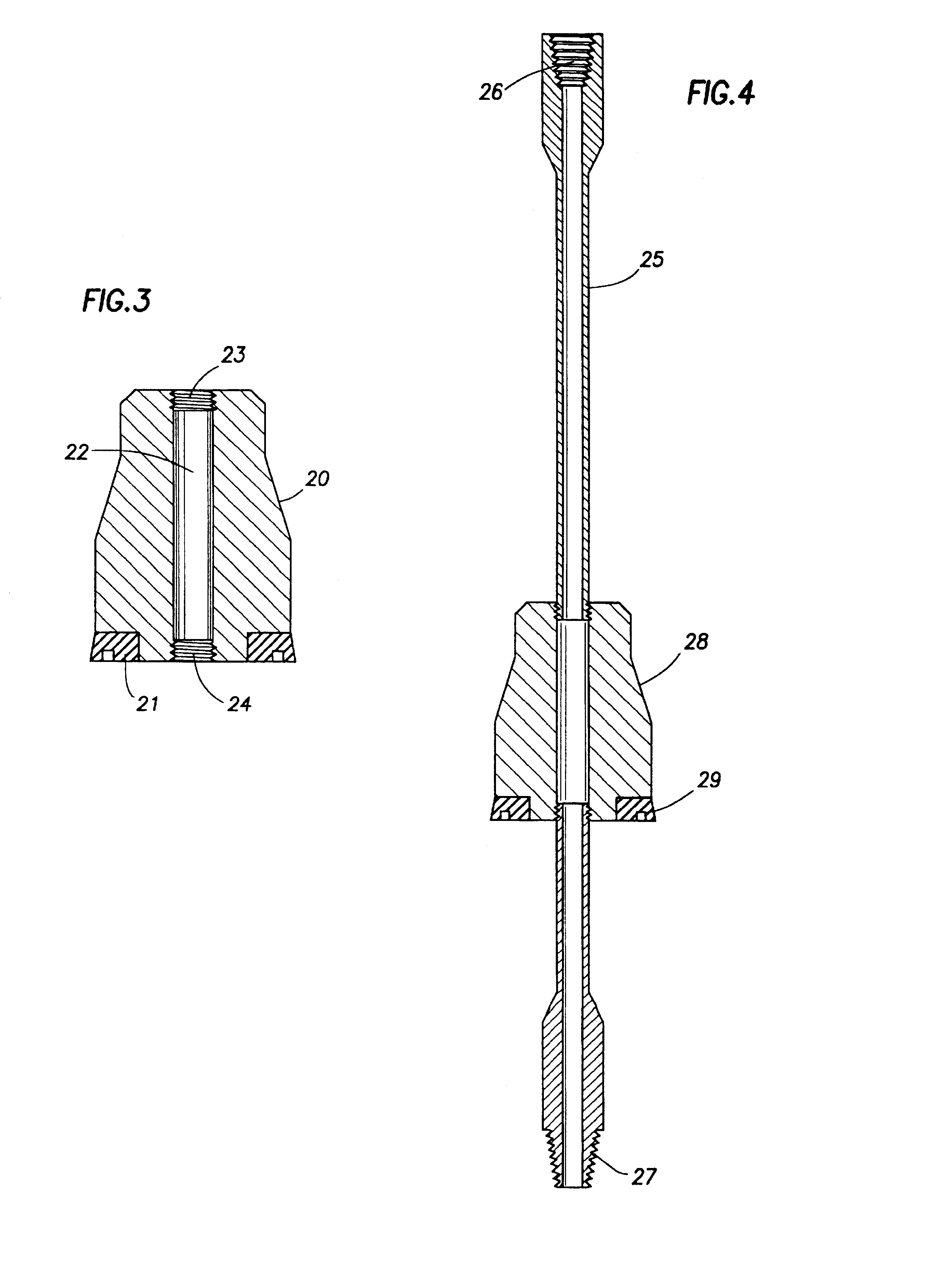
In yet further embodiments, the invention relates to a novel liner, which may additionally include expansion means therein; to an apparatus or tool for expansion of a liner having a reduced diameter section; and to a novel liner-die assembly or combination which is useful in cementing operations. More particularly, the liner of the invention comprises a wellbore liner having a .[.minor.]. section of reduced external and internal diameter composed of a deformable material and a .[.larger.]. remainder section of increased external and internal diameter. The expansion device or apparatus of the invention comprises unique fluid tight die means adapted for expansion of a liner section of reduced internal and external diameter, and preferably comprises a means for transmitting a fluid, e.g., a pipe; a die member adapted for expanding, at least substantially uniformly, the bore of a liner, on the periphery of said pipe; and sealing means positioned on the periphery of the die member adapted to provide a fluid tight seal between the bore of a liner and said die member. In the preferred arrangement, the pipe is provided at one end thereof with means for connecting the pipe to, or for suspending the pipe from, a drillstring, and is further preferably provided at the opposite end thereof with means for suspending a tool, preferably components used in cementing operations, and, especially, in one aspect of the invention, means to assist in sealing the end of the liner distant from said opposite end of the pipe.

Problems solved by technology

If the driller encounters an extended series of high pressure / low pressure configurations, the number of liners required under such circumstances may be such that the well cannot usefully be completed because of the continued reduction of the liner diameters required.
Again, a further problem of the standard well liner configuration is that large volumes of cuttings are produced initially, and heavy logistics are required during early phases of drilling.
While several approaches to the resolution of these problems have been attempted, none have proven totally satisfactory.

Method used


Image

  • Method and apparatus for cementing a well
  • Method and apparatus for cementing a well
  • Method and apparatus for cementing a well

Examples


Embodiment Construction

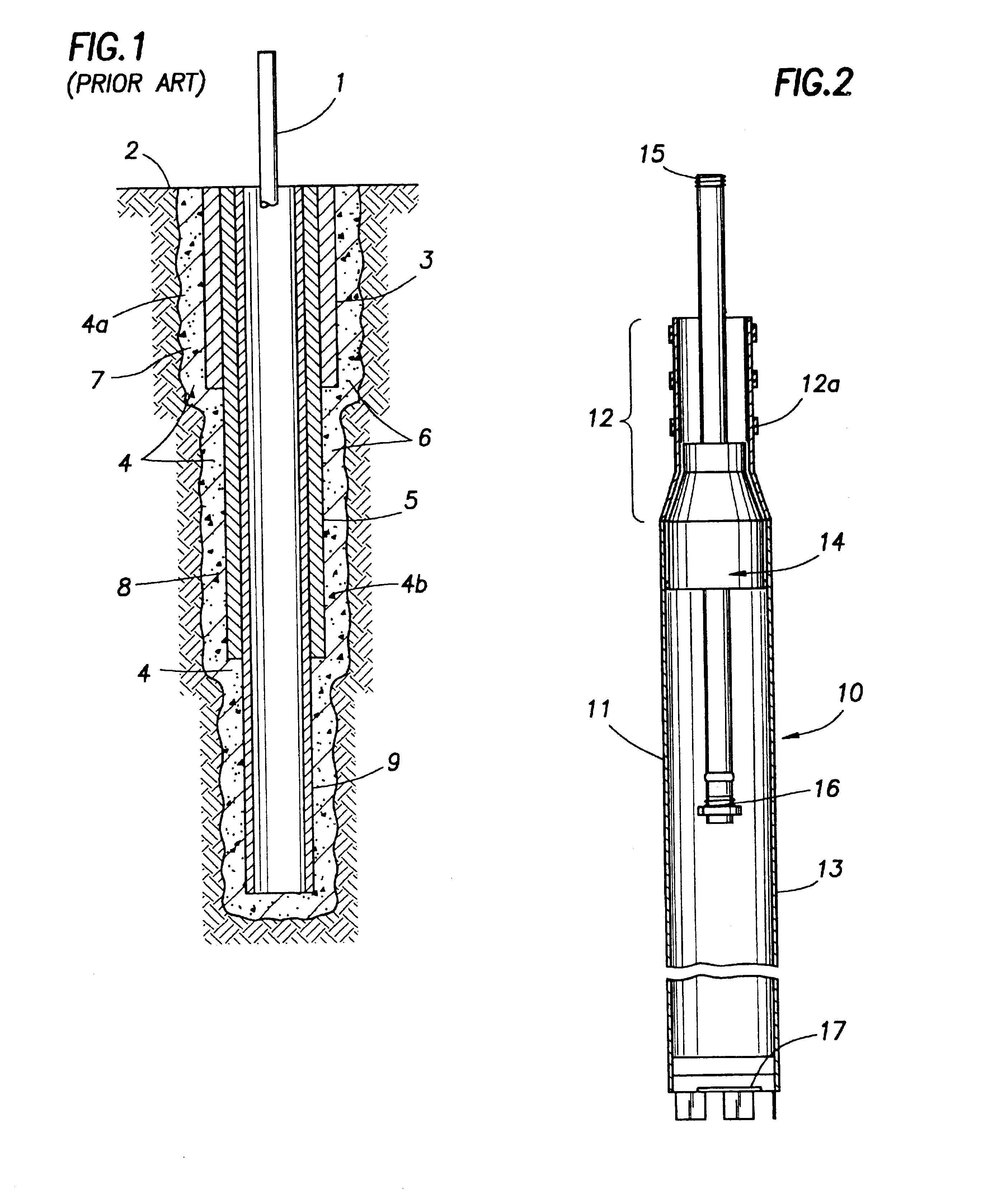
For a fuller understanding of the invention, reference is made to the drawing. Accordingly, in FIG. 1 there is shown a well string 1 extending to the earth surface 2 and to conductor pipe or casing 3. Conductor pipe 3 is positioned in the portion 4a of wellbore 4, while pipe 5 is in reduced diameter section 4b of the same wellbore. The wellbore forms segmented annulus 6 with pipes 3 and 5, the width of the annulus segments being the same or approximately the same. A further reduced diameter section 9 is illustrated. As indicated, standard cementing operations provide a cemented annulus which stabilizes the wellbore, but the effective diameter of the conducting passage is progressively and substantially reduced as the well is deepened.

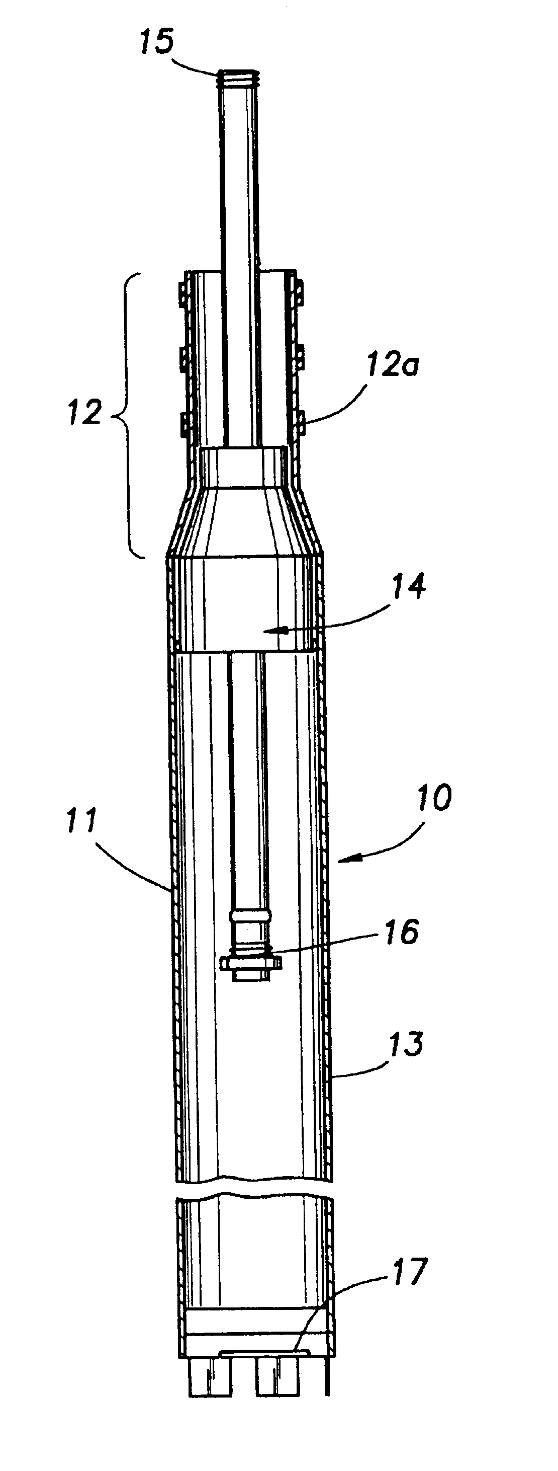
FIG. 2 illustrates an important aspect of the invention. Accordingly, in FIG. 2 there is shown a liner-die assembly designated generally as 10. The assembly includes the liner component 11 which, as shown, comprises a liner head section 12 which include...


PUM


Abstract

A method of cementing a well permitting a reduction in the degree of diameter reduction of casing or liners required, and not requiring excessively large initial conductor casing, is described. The method is characterized by provision of an enlarged wellbore and a novel liner structure which is adapted for expansion of a reduced diameter section thereof downhole, providing, before expansion of the section, unimpeded flow of fluid from the enlarged wellbore during cementing and close fit of the expanded section with the casing or preceding liner, after cementing is completed and expansion of the section. A novel well liner structure and novel well liner expansion means are disclosed.

Description

FIELD OF THE INVENTIONThis invention relates to a method for cementing a well and to apparatus useful in well cementing operations.BACKGROUND OF THE INVENTIONIn the conventional drilling of a well, such as an oil well, a series of casings and / or liners are commonly installed sequentially in the wellbore or borehole. In standard practice, each succeeding liner placed in the wellbore has an outside diameter significantly reduced in size when compared to the casing or liner previously installed. Commonly, after the installation of each casing or liner, cement slurry is pumped downhole and back up into the space or annulus between the casing or liner and the wall of the wellbore, in an amount sufficient to fill the space. The cement slurry, upon setting, stabilizes the casing or liner in the wellbore, prevents fluid exchange between or among formation layers through which the wellbore passes, and prevents gas from rising up the wellbore.The use of a series of liners which have sequentia...

Claims


Application Information

Patent Timeline
Patent Type & Authority Patents(United States)
IPC IPC(8): E21B23/08E21B23/00E21B33/14E21B43/10
CPCE21B33/14E21B43/105
Inventor VERCAEMER, CLAUDE J.DARLING, BRIAN
Owner SCHLUMBERGER TECH CORP
Learn More