Fuel injector armature guide

a fuel injector and guide surface technology, which is applied in the direction of fuel injection apparatus, wear-reducing fuel injection, feed system, etc., can solve the problems of high friction on the moving mass in the area of the guide surface, and achieve the effect of reducing the diameter

Inactive Publication Date: 2010-01-28
DELPHI TECH INC
View PDF6 Cites 1 Cited by
  • Summary
  • Abstract
  • Description
  • Claims
  • Application Information

AI Technical Summary

Benefits of technology

[0010]Briefly described, a system for guiding the moving mass of a solenoid-actuated injector includes a guide assembled in an axial location that is near the location of the magnetic forces imposed on the armature by the injector's solenoid. An armature of an armature / pintle assembly, in accordance with the invention, includes a reduced diameter section. In one aspect of the invention, the guide is shaped to surround the reduced diameter section of the armature and to extend under a main section of the armature. The outer circumferential contour of the reduced diameter section of the armature functions as a guide surface. This allows for a relative large guide length to diameter ratio.
[0011]The upper guide is supported and positioned by a collar formed in the lower housing of the fuel injector. The collar also serves to locate the lower housing in the injector assembly. Additionally, the lower housing of the fuel injector includes a feature, serving as a lower guide, for guiding the valve of the armature / pintle assembly and, accordingly, enables the concentricity of the lower guide and the upper guide to be tightly controlled.

Problems solved by technology

However, since the guide location is axially distanced from the location of the radial load imposed on the armature by the magnetic forces, the friction imposed on the moving mass in the area of the guide surface is high.

Method used


Image

  • Fuel injector armature guide
  • Fuel injector armature guide
  • Fuel injector armature guide

Examples


Embodiment Construction

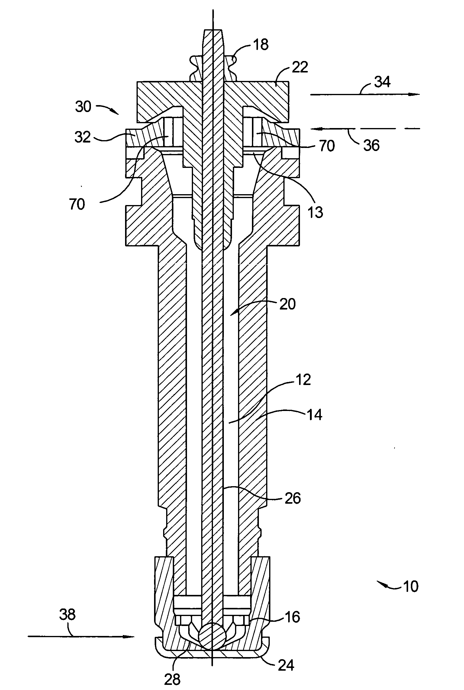
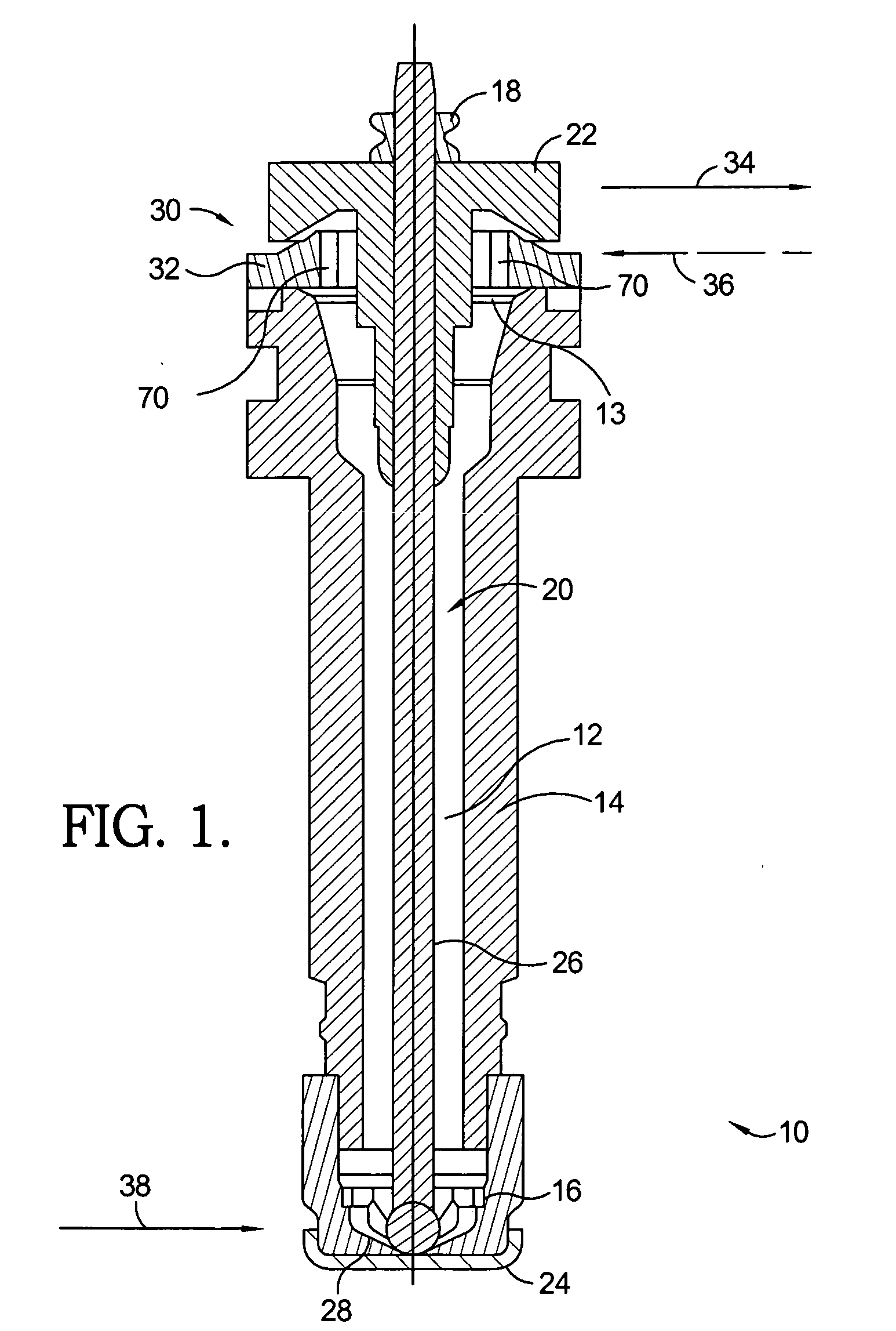
[0015]Referring to FIG. 1, a solenoid actuated fuel injector 10 includes a lower housing 12 enclosing a fuel passage 14, an armature / pintle assembly 20 disposed within fuel passage 14, and an upper guide system 30 and a lower guide system 16, both guiding armature pintle assembly 20.

[0016]Armature / pintle assembly 20 includes an armature 22 and a valve 24, such as a ball, positioned at opposite ends of a pintle 26. A valve seat 28 positioned at an end of lower housing 12 receives valve 24. Armature / pintle assembly 20 is assembled within lower housing 12 for reciprocating movement in axial direction within fuel passage 14.

[0017]Armature 22 is confined by but not fixed to pintle 26. This allows armature 22 to accelerate independent of pintle 26. A weld block 18 is fixed to an end of pintle 26 opposite from valve 24 and limits the axial upward movement of armature 22. When the moving mass of armature 22 collides with weld block 18, armature 22 rapidly lifts entire armature / pintle assemb...


PUM


Abstract

An upper guide system for a solenoid actuated fuel injector of an internal combustion engine includes an armature having a first diameter section, a reduced diameter second section, and a concave portion at the transition between the first and second sections. The guide system also includes a guide shaped to extend into the concave portion of the armature and includes a central opening that slidably receives the second diameter section. The guide positions and guides the armature in a radial and an axial direction. The guide is assembled in an axial location that is close to the axial location of the center of the magnetic force acting on the armature. The guide system allows for a desired relative large guide length to diameter ratio.

Description

TECHNICAL FIELD[0001]The present invention relates to fuel injection systems of internal combustion engines; more particularly, to solenoid actuated fuel injectors; and most particularly, to an upper guide system of an armature pintle assembly.BACKGROUND OF THE INVENTION[0002]Fuel injected internal combustion engines are well known. Fuel injection arrangements may be divided generally into multi-port fuel injection (MPFI), wherein fuel is injected into a runner of an air intake manifold ahead of a cylinder intake valve, and direct injection (DI), wherein fuel is injected directly into the combustion chamber of an engine cylinder, typically during or at the end of the compression stroke of the piston. DI is designed to allow greater control and precision of the fuel charge to the combustion chamber, resulting in better fuel economy and lower emissions. This is accomplished by enabling the combustion of a precisely controlled charge of fuel under various operating conditions. DI is al...

Claims


Application Information

Patent Timeline
Patent Type & Authority Applications(United States)
IPC IPC(8): F02M51/06
CPCF02M51/0653F02M51/0671F02M2200/9061F02M2200/02F02M2200/9038F02M51/0675
Inventor PERRY, ROBERT B.ALLEN, KEVIN J.COOPER, RICHARD L.
Owner DELPHI TECH INC
Why Eureka
Try Eureka