
Fastener system

a technology of fastener and flexible leg, which is applied in the direction of fastening means, screws, dowels, etc., can solve the problems of affecting the desired function of flexible leg, affecting affecting the operation of the flexible leg. , to achieve the effect of increasing the modularity of the aircraft's cabin, increasing the adaptability of aircraft manufacturing processes, and increasing manufacturing adaptability

Active Publication Date: 2021-12-07
CENTRIX
View PDF27 Cites 3 Cited by
  • Summary
  • Abstract
  • Description
  • Claims
  • Application Information

AI Technical Summary

Benefits of technology

The patent describes a fastener system that uses blind fasteners to secure two objects together. The system includes a sleeve and a collet body with a cantilever leg and a foot that mates with the sleeve. The system also includes a stud with a threaded section that engages with the collet body or the sleeve. The collet body protects the cantilever leg from shear stresses and the nonmetallic material of the collet body reduces wear during insertion and removal. The system allows for variable clamping force and easy installation and removal. The reduced diameter section allows for free rotation of the stud and the auxiliary structure enables quick and efficient removal of the system after it is unclamped. The technical effects of the fastener system include increased manufacturing adaptability, increased longevity of the fastener, and reduced likelihood of fastener degradation.

Problems solved by technology

However, the inventors have recognized several drawbacks with previous blind fasteners.
For instance, the collet body may be susceptible to shear stresses due to external structural loading and the external position of the collet body in the fastener.
As a result, individual flexible legs in prior fasteners can become substantially damaged and fail, or suffer other forms of damage (e.g., permanent deformation) that impede desired functions of the flexible legs.
The stud may be difficult to remove and in some cases become stuck within the collet body when the fastener clamps two adjoining structures.
Furthermore, the fingers in the collet body may be difficult to insert into a bore due to the exposed edges of the collet body fingers now deformed and protruding radially outward, due to damage sustained in resisting shear.
Moreover, when the collet body is constructed out of a nonmetallic material, such as a polymer, the sleeve protects the collet body from abrasive wear during insertion and removal, decreasing the likelihood of fastener degradation.

Method used


Image

  • Fastener system
  • Fastener system
  • Fastener system

Examples


Embodiment Construction

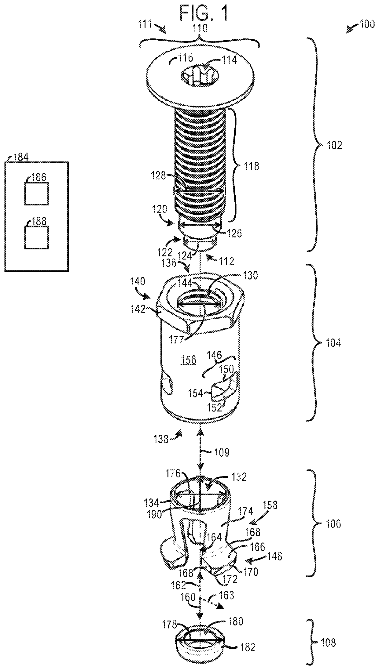
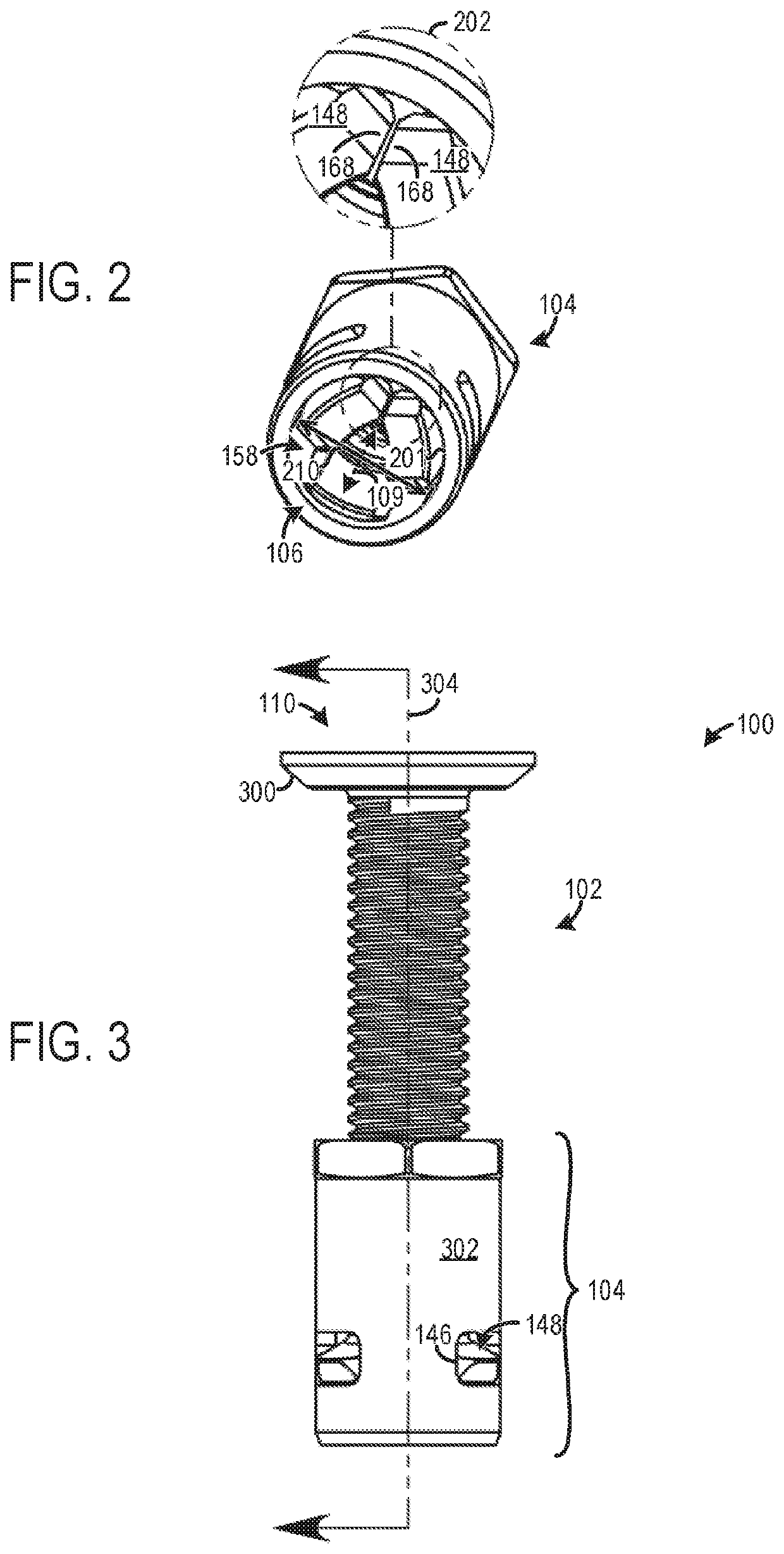
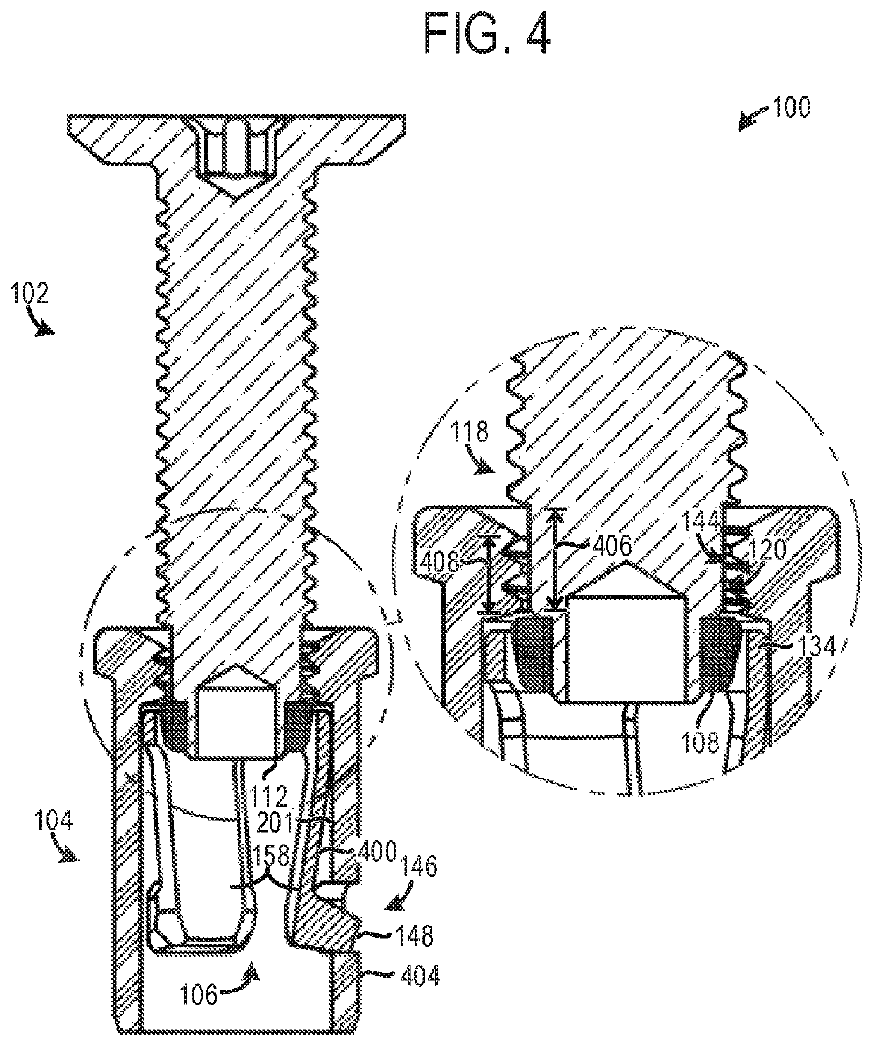
[0034]The following description relates a fastener system designed to decouple shear stresses from a collet body and provide clamping engagement to targeted structures. Decoupling of the shear stresses from the collet body enables quick, efficient, and unobstructed engagement and disengagement of clamping arms in the system. In particular, the fastener system is designed to decouple shear forces from a weaker section (i.e., cantilever legs) and place the same shear forces onto a much stronger section (i.e., a sleeve). As a result, the fastener system has excess capacity, enabling the system to carry additional shear forces. The fastener system includes a collet body that fits within a sleeve. The collet body is provided with feet on the end of cantilever legs extending downward from a crown. When the fastener system is in an engaged configuration and a stud is threaded into the collet body and sleeve, the feet protrude through openings in the sleeve. The sleeve protects the collet b...


PUM


Abstract

A fastener system shifting shear stresses away from a collet body and provides clamping action to targeted structures. The fastener system includes feet in the collet body that mate with openings in a sleeve at least partially surrounding the collet body. The sleeve or the collet body includes interior threads that engage with a stud that is configured to extend through the collet body and bend the feet such that they project outward from the sleeve openings in an engaged configuration.

Description

CROSS REFERENCE TO RELATED APPLICATION[0001]The present application claims priority to U.S. Provisional Application No. 62 / 558,762, entitled “Fastener System”, and filed on Sep. 14, 2017. The entire contents of the above-listed application are hereby incorporated by reference for all purposes.FIELD[0002]The present description relates generally to a fastener system designed to clamp two structures.BACKGROUND AND SUMMARY[0003]Many manufacturing fields use fasteners, such as blind fasteners, for securing two objects to one another. Blind fasteners are particularly useful when only one side of a joint is accessible. One application of such fasteners is in the aerospace industry where removable collet fasteners are utilized to secure floor panels to underlying floor beams. Using removable fasteners to secure floor panels to the floor beams increases the modularity of the aircraft's cabin. Resultantly, the aircraft's interior may be altered at a late stage in manufacturing to increase th...

Claims


Application Information

Patent Timeline
Patent Type & Authority Patents(United States)
IPC IPC(8): F16B5/00F16B5/02F16B19/10F16B13/10
CPCF16B5/0258F16B19/109F16B19/1081F16B2013/10F16B13/068F16B13/10
Inventor MCCLURE, TRAVIS
Owner CENTRIX
Learn More