Hook for hook and loop fasteners

a technology of hooks and loops, applied in the field of improved hooks for hooks and loops, can solve the problems of many other prior art hooks, insufficient displacement volume calculation, and inability to function effectively with very low profile loops, and achieve the effect of enhancing the performance of such hooks

Inactive Publication Date: 2004-11-16
VELCRO IND BV
View PDF159 Cites 14 Cited by
  • Summary
  • Abstract
  • Description
  • Claims
  • Application Information

AI Technical Summary

Benefits of technology

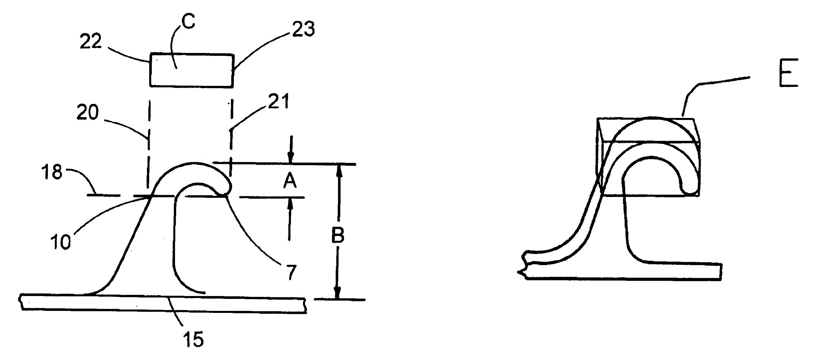
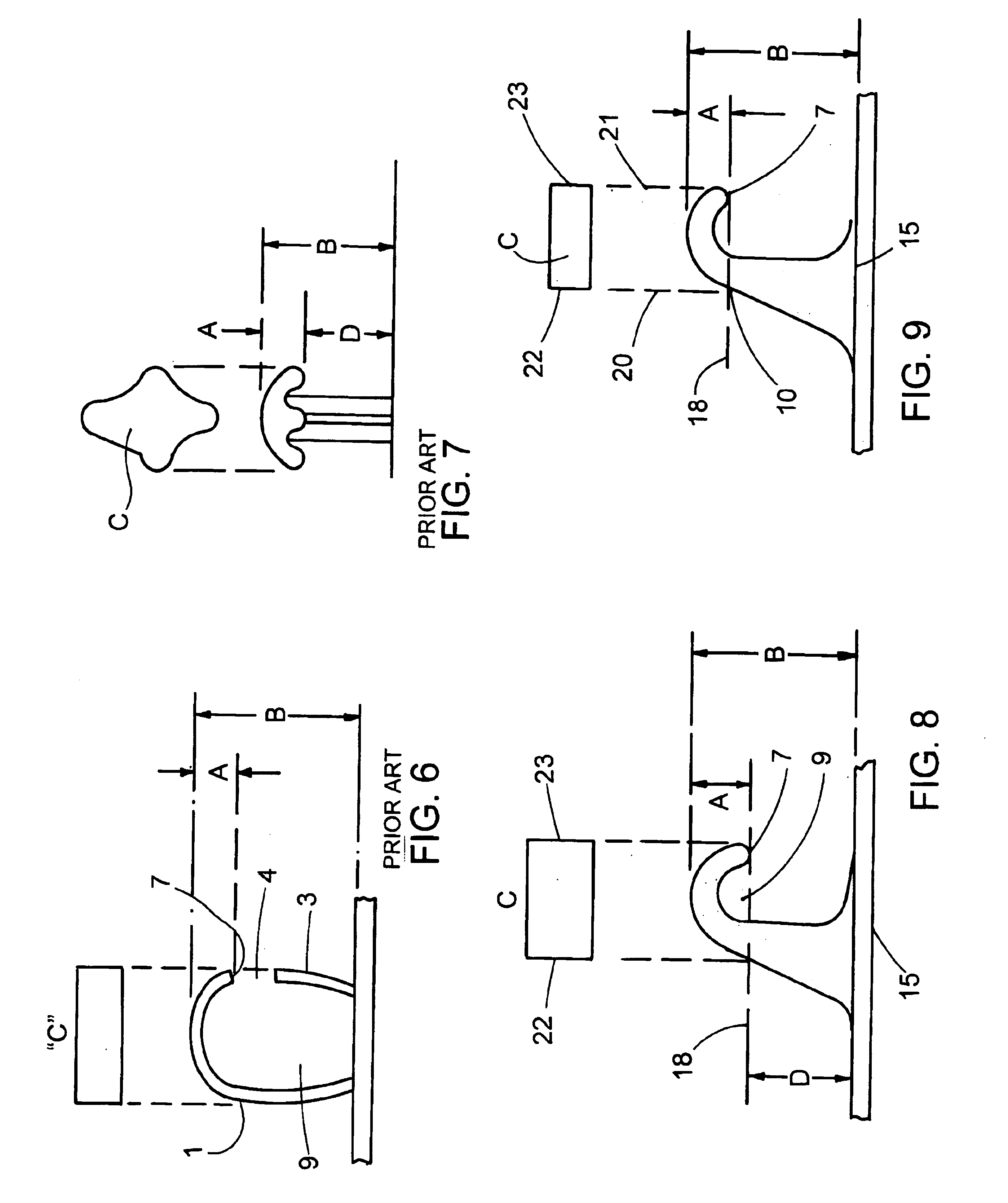
The present invention contemplates producing a hook from the method described in U.S. Pat. No. 4,794,028 to Fischer in which both the size and shape of the hook is especially suited to low level loops. It has been found that outstanding and unexpected performance from such hooks in low level loops is possible. It is further realized that the selection of the appropriate resin greatly enhances the performance of such hooks. More specifically I have found that a hook produced with a displacement volume, discussed more fully below, of less than 6.times.10.sup.-6 cubic inches and preferably a displacement volume of less than 4.times.10.sup.-6 cubic inches will provide unusual and outstanding performance with a loop of the lowest loop configuration. Displacement volume, as defined herein, is the volume of a rectangular parallelepiped which delineate the volume of loop displaced when a hook penetrates into the loop to just the point where loops may start to fall into the cavity at the inside of the crook of a hook, as will be more fully appreciated from the description below.

Problems solved by technology

The dimensions disclosed and claimed in the Nestegard patent are not sufficient to calculate a displacement volume.
While the hooks formed according to these patents posses many useful properties and engage with a wide range of loop constructions, they possess the limitations of many other prior art hooks in their inability to function effectively with very low profile loops constructed with very short individual loops.
In general, however, such loops do not function well with conventional hook structures.
However, mushroom products have many disadvantages.
They are limited to use of orientated polypropylene fibers with associated limitations of that material, such as a relatively low temperature operating range.
The mushroom heads are easily snapped off their stems giving such products very limited life in use, and the mushroom head does not have the flexing capability of a hook shape and therefore the only way a loop can be removed from the head is to rupture either the loop or the mushroom head.
Other limitations of mushroom products are well known to those in the art.

Method used


Image

  • Hook for hook and loop fasteners
  • Hook for hook and loop fasteners
  • Hook for hook and loop fasteners

Examples


Embodiment Construction

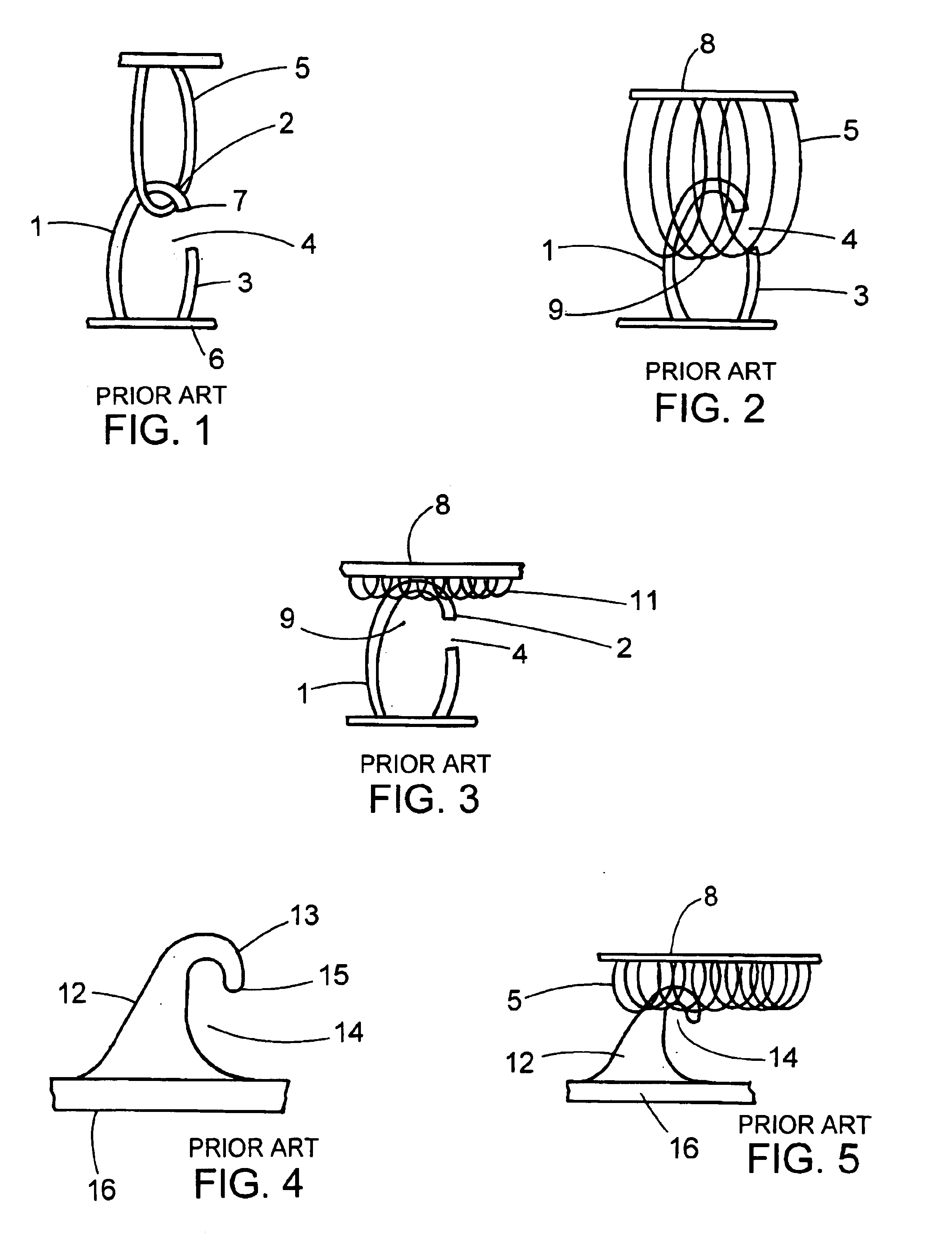
Now referring to FIG. 1, a monofilament (1) strand is bent into a loop shape which is cut along one side of the loop to create the crook(2) of a hook with a residual portion(3) of the monofilament loop separated from the hook end tip(7) of the hook to provide a spaced opening(4) sufficient to permit loop(5) to enter and become entangled within the crook(2). In FIG. 6 the dimension "A" of the hook (1) represents the dimension of the return, or height of the crook, while "B" represents the total height of the hook from its base(6) to the top outside of the crook(2). The rectangle "C" of FIG. 6 represents the footprint of material that penetrates into a loop structure when penetration is just sufficient to position tip (7) below the top of a loop. FIG. 2 illustrates what happens when the hook(1) attempts to penetrate into a mat of loops. The top of the hook, having a footprint as shown in FIG. 6 "C", pushes aside the loops(5) and continues to penetrate into the loop pile until it strik...


PUM

PropertyMeasurementUnit
heightaaaaaaaaaa
thicknessaaaaaaaaaa
heightaaaaaaaaaa

Abstract

A plastic molded hook for use with a hook and loop fastening system especially adapted for use with low profile loops. The hook design includes a base, a stem and a crook whereby the volume of the portion of the hook penetrating into a pile of loops is defined as the displacement volume. Hooks especially adapted for use with low profile loops have a displacement volume of less than 6.times.10.sup.-6 cubic inches.

Description

BACKGROUND OF THE INVENTIONThis invention relates to an improved hook for hook and loop fasteners and particularly to plastic molded hooks intended for use with low pile loops. The technology of hook and loop fasteners is well known wherein a fastener comprised of two separable pile fastening tapes have interengaging piles on their surfaces, one pile have loop-elements and the other hook elements, are capable of co-acting to form a separable bond.Such pile fasteners have found a wide variety of uses where ease of opening and closing is desirable such as in clothing, footwear, home furnishings, medical products, automotive fastening and many other industrial situations where detachable or permanent engagement is required. U.S. Pat. No. 3,009,235, U.S. Pat. No. 3,083,737 and U.S. Pat. No. 3,154,837 disclose various forms of separable pile fastener tapes constructed from fibrous forms of synthetic polymers such as nylon using basic textile weaving techniques. Such methods create a base...

Claims


Application Information

Patent Timeline
Patent Type & Authority Patents(United States)
IPC IPC(8): A44B18/00
CPCA44B18/0061Y10T24/2792Y10T24/27Y10T24/2742Y10T24/2767Y10T24/275
Inventor PROVOST, GEORGE A.
Owner VELCRO IND BV
Why Eureka
Try Eureka